2-10
BE1-BPR Application
Breaker Failure Protection With Pre-Insertion Resistors
Breakers that will be exposed to fault currents above the maximum rated interrupting capacity are normally
equipped with pre-insertion resistors. Pre-insertion resistors are mechanically placed in series with the
breaker interrupting contacts when the breaker opens. This reduces the current magnitude until the fault is
cleared a cycle or more later.
Typically, the BE1-BPR fault detector is set to pickup below the minimum pre-insertion resistor current level
to insure that the breaker has opened and the fault cleared. Sometimes, system stability requires faster
clearing times and closer margins on breaker failure timing. The BE1-BPR can be configured to provide a
faster BF clearing time for an initial higher fault current level, and slower BF clearing time for lower level fault
currents that are limited by the pre-insertion resistors.
This adaptive breaker failure logic can be configured by making use of the additional fault detectors and
timers available in the BE1-BPR. One BF delay timer would be set to the maximum time allowed for the
higher fault current level to be cleared and maintain system stability. The output would be ANDed with a fault
detector set to detect this higher fault current level. This fault detector will drop out when the current is
reduced because the pre-insertion resistor is inserted. Another BF delay timer would be set for a longer time
based on the maximum time allowed for the lower current level fault to be cleared. This timer output would
be ANDed with a different fault detector set to pickup on pre-insertion resistor current levels. The output of
both AND gates would be ORed so that either one would drive the BF output.
This logic provides improved security and protection for breaker failure by providing two timing margins and
two different fault current levels. See
BFRES logic in BE1-BPR Custom Application Schemes, Section 5,
Programmable Logic, for a specific application example.
Note that the preprogrammed breaker failure logic schemes in the BE1-BPR relay do not provide breaker
failure protection for the single-pole tripping of breakers with pre-insertion resistors. This is because the fault
detector level would have to be set at a level that is less than the normal load current. Therefore, the phase
fault detector would stay picked up because of the load current on the non-faulted phases.
Breaker Contact Duty Log
Breaker contact duty log is a diagnostic feature to monitor the number of times a breaker has operated and
accumulate the total contact duty or wear based on the current interrupted. The log is contained in the form
of an
I
2
t for each pole of the breaker. The total is reported as a percent of maximum for simplicity. If the
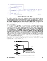
total exceeds the maximum programmed for any breaker pole, an internal diagnostic flag, Figure 2-14
becomes TRUE. In the preprogrammed logic schemes, the programmable diagnostic output (O14 or O15)
can be enabled using the PDIAG command to turn on the Alarm output to signal the operator that
maintenance is needed.
See
Section 4, Functional Description, for a detailed functional description on how to program the duty log
diagnostic feature.
Содержание BE1-BPR
Страница 1: ...Publication 9 2720 00 990 Revision E 12 98 INSTRUCTION MANUAL for BE1 BPR BREAKER PROTECTION RELAY...
Страница 31: ...BE1 BPR Application 2 17...
Страница 41: ...BE1 BPR Human Machine Interface 3 3 Figure 3 3 BE1 BPR Relay Horizontal Mount Front And Rear Views...
Страница 42: ...3 4 BE1 BPR Human Machine Interface Figure 3 4 BE1 BPR Relay Vertical Mount Front View...
Страница 43: ...BE1 BPR Human Machine Interface 3 5 Figure 3 5 BE1 BPR Relay Vertical Mount Rear View...
Страница 49: ...4 6 BE1 BPR Functional Description Figure 4 2 Enhanced BE1 BPR Menu Display Screens...
Страница 50: ...BE1 BPR Functional Description 4 7 Figure 4 3 Standard BE1 BPR Menu Display Screens...
Страница 94: ...5 4 BE1 BPR BESTlogic Figure 5 1 BESTlogic Function Blocks...
Страница 120: ...7 2 BE1 BPR Installation Figure 7 1 Overall Dimensions Figure 7 2 Cutout Dimensions Panel Mount...
Страница 121: ...BE1 BPR Installation 7 3 Figure 7 3 Overall Dimensions Vertical Mount...
Страница 122: ...7 4 BE1 BPR Installation Figure 7 4 Overall Dimensions Side View Vertical Mount...
Страница 123: ...BE1 BPR Installation 7 5 Figure 7 5 Panel Drilling Diagram Vertical Mount...

