BE1-BPR Application
2-11
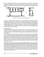
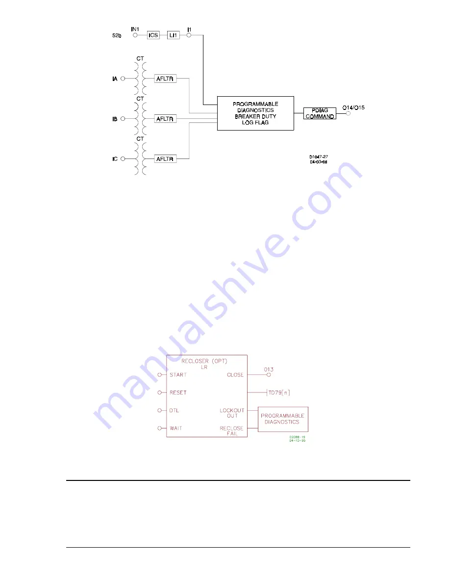
Figure 2-14. Breaker Contact Duty Log Circuits
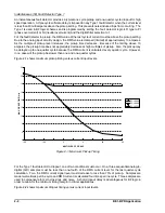
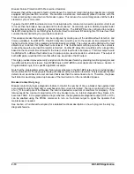
Figure 2-15. Reclosing Logic Circuit
Reclosing Functions
A Reclosing Function is available in the BE1-BPR relay that can operate in parallel with the breaker failure
logic. All inputs are programmable using the BESTlogic LR command. When reclosing is enabled, output
13 (O13) is designated at the reclose (close) output and can be connected to any physical output by using
the LO command. Three reclosing shots are available.
Separate time delays are programmable through the front panel or serial port by using the TD79 command.
Time delay settings are available for each shot (TD791, TD792 and TD793), for the reset timer (TD79R),
reclose fail timer (TD79F) and a maximum reclose cycle timer (TD79M). Lockout and reclose fail diagnostic
flags are set/reset by the programmable diagnostics. Use the PDIAG command to program separate outputs
for lockout and reclose fail. The reclosing state (RESET, WAIT, TIMING, or LOCKOUT) can be viewed from
the front panel recloser status screen in the relay status menu or by using the STATUS command.
There are four reclose function inputs, three available outputs, and one mode programmable feature (TYPE).
The inputs and outputs are shown in Figure 2-15.
PREPROGRAMMED LOGIC DESCRIPTION
BE1-BPR relays are factory programmed with protection schemes that provide breaker failure protection for
most systems. These preprogrammed breaker failure logic schemes are described in the following
paragraphs. The programmable logic equations are not provided in this description. See
Section 5,
Programmable Logic, for information on the description and use of the programmable logic as well as
application hints for programming custom logic.
Содержание BE1-BPR
Страница 1: ...Publication 9 2720 00 990 Revision E 12 98 INSTRUCTION MANUAL for BE1 BPR BREAKER PROTECTION RELAY...
Страница 31: ...BE1 BPR Application 2 17...
Страница 41: ...BE1 BPR Human Machine Interface 3 3 Figure 3 3 BE1 BPR Relay Horizontal Mount Front And Rear Views...
Страница 42: ...3 4 BE1 BPR Human Machine Interface Figure 3 4 BE1 BPR Relay Vertical Mount Front View...
Страница 43: ...BE1 BPR Human Machine Interface 3 5 Figure 3 5 BE1 BPR Relay Vertical Mount Rear View...
Страница 49: ...4 6 BE1 BPR Functional Description Figure 4 2 Enhanced BE1 BPR Menu Display Screens...
Страница 50: ...BE1 BPR Functional Description 4 7 Figure 4 3 Standard BE1 BPR Menu Display Screens...
Страница 94: ...5 4 BE1 BPR BESTlogic Figure 5 1 BESTlogic Function Blocks...
Страница 120: ...7 2 BE1 BPR Installation Figure 7 1 Overall Dimensions Figure 7 2 Cutout Dimensions Panel Mount...
Страница 121: ...BE1 BPR Installation 7 3 Figure 7 3 Overall Dimensions Vertical Mount...
Страница 122: ...7 4 BE1 BPR Installation Figure 7 4 Overall Dimensions Side View Vertical Mount...
Страница 123: ...BE1 BPR Installation 7 5 Figure 7 5 Panel Drilling Diagram Vertical Mount...


