BE1-BPR Manual Change Information
10-1
SECTION 10 • MANUAL CHANGE INFORMATION
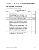
SUMMARY AND CROSS REFERENCE GUIDE
This section summarizes the changes made to the current edition and previous editions of the manual.
Manual revisions to date are summarized in Table 10-1.
Table 10-1. Instruction Manual Changes
Revision
Change
ECA/ECO
Date
A
Revised the entire manual to reflect changes in the relay that
added reclosing functions.
15067
04-18-95
B
Made revisions throughout manual to reflect the vertical
mounting option. Added Figures 3-4, 7-3, 7-4, and 7-5 to show
vertical mount. Minor corrections made in
Reclosing Mode and
FLOG Command. Corrected figure 4-2.
15159
07-20-95
C
Revised manual to include changes resulting from adding
IRIG-B functions (ECA 15457).
15494
01-29-96
D
Manual was revised to reflect changes made in firmware
version 3.26. The “r” parameter range of the LI command was
changed from 1-255 to 4-255. Password access areas were
expanded to four areas; area 4 enables output contacts to be
pulsed for testing. The CTI, DLOG, LO13, LO14, and LO15
settings were removed from all SHOWSET settings report
examples.
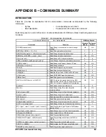
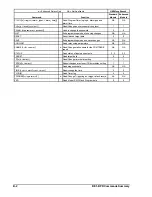
COMMAND information was summarized in tables. Missing
command setting range information was added. Various
inaccuracies were corrected. Figure 7-5,
Panel Drilling
Diagram (Vertical Mount) was updated. Setup instructions for
using Windows
®
Terminal and HyperTerminal
®
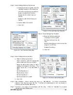
were added.
Added Figure 7-13 to show how connections are made to SEL-
2020. Updated/clarified calibration and testing procedures of
Section 8. Updated the manual style and added an index.
267
09-14-98
E
Revised the manual to change pg. 1-7
Output Relay Pickup
Time, Output 1 from “1/4 cycle (4.2 milliseconds) maximum” to
“4 milliseconds typical, 5 milliseconds maximum.”
1046
12-10-98
Содержание BE1-BPR
Страница 1: ...Publication 9 2720 00 990 Revision E 12 98 INSTRUCTION MANUAL for BE1 BPR BREAKER PROTECTION RELAY...
Страница 31: ...BE1 BPR Application 2 17...
Страница 41: ...BE1 BPR Human Machine Interface 3 3 Figure 3 3 BE1 BPR Relay Horizontal Mount Front And Rear Views...
Страница 42: ...3 4 BE1 BPR Human Machine Interface Figure 3 4 BE1 BPR Relay Vertical Mount Front View...
Страница 43: ...BE1 BPR Human Machine Interface 3 5 Figure 3 5 BE1 BPR Relay Vertical Mount Rear View...
Страница 49: ...4 6 BE1 BPR Functional Description Figure 4 2 Enhanced BE1 BPR Menu Display Screens...
Страница 50: ...BE1 BPR Functional Description 4 7 Figure 4 3 Standard BE1 BPR Menu Display Screens...
Страница 94: ...5 4 BE1 BPR BESTlogic Figure 5 1 BESTlogic Function Blocks...
Страница 120: ...7 2 BE1 BPR Installation Figure 7 1 Overall Dimensions Figure 7 2 Cutout Dimensions Panel Mount...
Страница 121: ...BE1 BPR Installation 7 3 Figure 7 3 Overall Dimensions Vertical Mount...
Страница 122: ...7 4 BE1 BPR Installation Figure 7 4 Overall Dimensions Side View Vertical Mount...
Страница 123: ...BE1 BPR Installation 7 5 Figure 7 5 Panel Drilling Diagram Vertical Mount...


