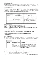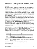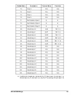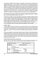
BE1-BPR BESTlogic
5-9
Outputs may be programmed to be normally energized (ALARM output) or de-energized; e.g., BFO. Outputs
OUT1 through OUT4 are jumper selectable for normally open (NO) or normally closed (NC) contacts.
Changing an output contact’s configuration requires moving a soldered jumper located on the printed circuit
board. Caution should be taken with NC outputs because there are no shorting bars to maintain the closed
condition if the electronics are removed from the chassis. In situations where a NC contact is required even
when the electronics are removed, it is recommended that a NO output be used to drive an external low cost
auxiliary relay. The NC output of the auxiliary relay can then be used and the electronics can still be drawn
out. Alternately, an external switch can be used to short across the NC output when the electronics are
removed. Extra care is required to make sure this is done and that the short is removed once the electronics
are reinstalled.
BE1-BPR PREPROGRAMMED PROTECTION SCHEMES
Each BE1-BPR relay comes with a number of preprogrammed breaker failure logic schemes that are
preprogrammed into non-volatile memory. Section 2,
Application contains descriptions of the logic schemes
and their applications.
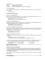
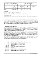
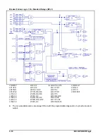
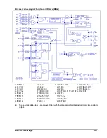
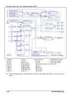
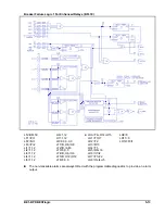
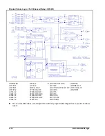
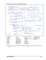
For reference, each of the preprogrammed schemes and their corresponding logic equations are provided
on the following pages.
Содержание BE1-BPR
Страница 1: ...Publication 9 2720 00 990 Revision E 12 98 INSTRUCTION MANUAL for BE1 BPR BREAKER PROTECTION RELAY...
Страница 31: ...BE1 BPR Application 2 17...
Страница 41: ...BE1 BPR Human Machine Interface 3 3 Figure 3 3 BE1 BPR Relay Horizontal Mount Front And Rear Views...
Страница 42: ...3 4 BE1 BPR Human Machine Interface Figure 3 4 BE1 BPR Relay Vertical Mount Front View...
Страница 43: ...BE1 BPR Human Machine Interface 3 5 Figure 3 5 BE1 BPR Relay Vertical Mount Rear View...
Страница 49: ...4 6 BE1 BPR Functional Description Figure 4 2 Enhanced BE1 BPR Menu Display Screens...
Страница 50: ...BE1 BPR Functional Description 4 7 Figure 4 3 Standard BE1 BPR Menu Display Screens...
Страница 94: ...5 4 BE1 BPR BESTlogic Figure 5 1 BESTlogic Function Blocks...
Страница 120: ...7 2 BE1 BPR Installation Figure 7 1 Overall Dimensions Figure 7 2 Cutout Dimensions Panel Mount...
Страница 121: ...BE1 BPR Installation 7 3 Figure 7 3 Overall Dimensions Vertical Mount...
Страница 122: ...7 4 BE1 BPR Installation Figure 7 4 Overall Dimensions Side View Vertical Mount...
Страница 123: ...BE1 BPR Installation 7 5 Figure 7 5 Panel Drilling Diagram Vertical Mount...

