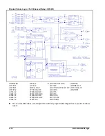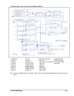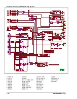
BE1-BPR BESTlogic
5-7
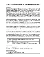
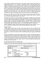
LO Command
Purpose:
Reads or programs output logic
Syntax:
LO [#[=<Boolean equation>]]
Comments:
Access area one password is required to change setting.
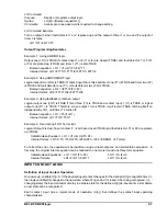
LO Command Example
Turn on output 1 when fault detector 1 or 2 is picked up and the output of timer 1 is true and the output of
timer 3 is false.
LO1=(F1+F2)T1/T3
Output Programming Examples
Example 1: Using AND/OR logic
Output one (LO1) is TRUE if contact input 1 or 2 (I1 or I2) are closed (TRUE) and fault detector 1 or 2 (F1
or F2) are picked-up (TRUE) and timer 1 (T1) is also TRUE.
Boolean equation: LO1 = (I1+I2)*(F1+F2)*T1
Internal format: LO1=F2T1I2
Example 2: Using AND/OR/NOT logic
Logical output two (LO2) is TRUE if contact input two is false and timer one (T1) is TRUE and timer two (T2)
is TRUE and fault detector one (F1) or fault detector two (F2) is TRUE.
Boolean equation: LO2 = /I2T1T2(F1+F2)
Internal format: LO2=F1T1T2/I2+F2T1T2/I2
Example 3: Using feedback to latch an output
Logical output one (LO1) is TRUE if timer three (T3) is TRUE and contact input 1 (I1) is TRUE or logical
output one (O1) is TRUE. Therefore, when output 1 turns TRUE, it will remain TRUE, latching itself on
independently of I1, until timer T3 turns off.
Boolean equation: LO1 = T3(I1+O1)
Internal format: LO1=T3I1+T3O1
Example 4: Overcoming 4 OR Term Limit
Logical Output 2 is true if input contact I1, I2 or I3 are closed (TRUE) and fault detector F1 or F2 are picked-
up (TRUE).
Initial Boolean Equation: LO1 = (I1+I2+I3)(F1+F2)
Internal format: LO1=I1F1+I1F2+I2F1+I2F2+I3F1+I3F2 (ERROR: >4 Terms)
To correct the error, the equation will be rewritten using a virtual output as an intermediate expression. In
this way, the original 6 term equation can be reduced to one two term and one three term equation.
Initial Boolean Equations: LO1 = O11(F1+F2)
LO11=I1+I2+I3
Internal formats:
LO1=F1O11+F2O11
LO11=I1+I2+I3
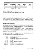
INPUT CONTACT LOGIC
Definition of Input Contact Operation
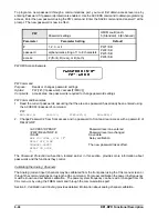
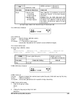
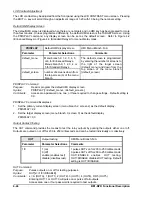
On power-up, variable I[n] = 0. If the physical input contact changes for the defined LI[n] recognition time (r),
then logic variable I[n] changes to the new state, where 0=open and 1=closed. After being recognized, (i.e. -
changing state) the input contact must stay in a stable state for the defined LI[n] de-bounce time (db) before
a new state can be recognized.
Each contact input has a logical mode of operation (LI[n]) that defines the contact input operating
characteristics.
Содержание BE1-BPR
Страница 1: ...Publication 9 2720 00 990 Revision E 12 98 INSTRUCTION MANUAL for BE1 BPR BREAKER PROTECTION RELAY...
Страница 31: ...BE1 BPR Application 2 17...
Страница 41: ...BE1 BPR Human Machine Interface 3 3 Figure 3 3 BE1 BPR Relay Horizontal Mount Front And Rear Views...
Страница 42: ...3 4 BE1 BPR Human Machine Interface Figure 3 4 BE1 BPR Relay Vertical Mount Front View...
Страница 43: ...BE1 BPR Human Machine Interface 3 5 Figure 3 5 BE1 BPR Relay Vertical Mount Rear View...
Страница 49: ...4 6 BE1 BPR Functional Description Figure 4 2 Enhanced BE1 BPR Menu Display Screens...
Страница 50: ...BE1 BPR Functional Description 4 7 Figure 4 3 Standard BE1 BPR Menu Display Screens...
Страница 94: ...5 4 BE1 BPR BESTlogic Figure 5 1 BESTlogic Function Blocks...
Страница 120: ...7 2 BE1 BPR Installation Figure 7 1 Overall Dimensions Figure 7 2 Cutout Dimensions Panel Mount...
Страница 121: ...BE1 BPR Installation 7 3 Figure 7 3 Overall Dimensions Vertical Mount...
Страница 122: ...7 4 BE1 BPR Installation Figure 7 4 Overall Dimensions Side View Vertical Mount...
Страница 123: ...BE1 BPR Installation 7 5 Figure 7 5 Panel Drilling Diagram Vertical Mount...

