8-4
BE1-BPR Calibration And Testing
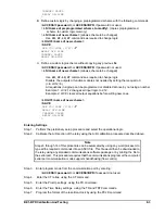
Step 8.
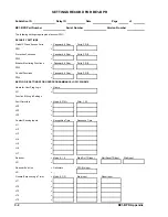
Program the service diagnostic alarms by using the PDIAG command.
Step 9.
Program the primary display screen (default screen when no targets are latched) by using the
PDISPLAY command.
Step 10. Program the Target operation by using the PTARGET command.
Step 11. Program the Timer Log settings by using the PTLOG command.
Step 12. Enter the communication settings using the COM command.
Step 13. Enter Passwords using the PW command.
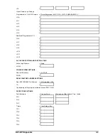
Step 14. If the breaker status is monitored, entered the breaker close logic and initial operations count by
using the BKROPS command.
Step 15. If the fault recording option is installed, enter the station name and number in the relay by using
the SNAME command and enter the fault trigger logic using the TRIGGER command.
Step 16. If the relay is monitoring a breaker with an opening resistor then enter the breaker resistor
information by using the BKRRES commands.
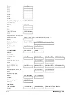
Step 17. If the relay has the breaker contact duty log option, then enter the breaker contact data by using
the BKRCON command and enter the initial breaker contact duty by using the DLOG command.
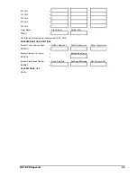
Step 18. Save the new settings using the SAVE command.
Step 19. Verify the new commands are correct by using the SHOWSET command.
Operational Testing
Step 1.
Use the PDIAG command to check for any diagnostic problems.
Use DIAG=0 to clear diagnostic log.
Step 2.
Connect a current source to any current input.
Step 3.
Verify that the logic scheme selected is operating as desired by simulating fault conditions with
the current source and input contacts.
Step 4.
Record the relay serial number, part number, logic, and operational settings for future reference.
This can be done easily with any standard communication program by opening a file and then
saving the relay response to the VER and SHOWSET commands.
Содержание BE1-BPR
Страница 1: ...Publication 9 2720 00 990 Revision E 12 98 INSTRUCTION MANUAL for BE1 BPR BREAKER PROTECTION RELAY...
Страница 31: ...BE1 BPR Application 2 17...
Страница 41: ...BE1 BPR Human Machine Interface 3 3 Figure 3 3 BE1 BPR Relay Horizontal Mount Front And Rear Views...
Страница 42: ...3 4 BE1 BPR Human Machine Interface Figure 3 4 BE1 BPR Relay Vertical Mount Front View...
Страница 43: ...BE1 BPR Human Machine Interface 3 5 Figure 3 5 BE1 BPR Relay Vertical Mount Rear View...
Страница 49: ...4 6 BE1 BPR Functional Description Figure 4 2 Enhanced BE1 BPR Menu Display Screens...
Страница 50: ...BE1 BPR Functional Description 4 7 Figure 4 3 Standard BE1 BPR Menu Display Screens...
Страница 94: ...5 4 BE1 BPR BESTlogic Figure 5 1 BESTlogic Function Blocks...
Страница 120: ...7 2 BE1 BPR Installation Figure 7 1 Overall Dimensions Figure 7 2 Cutout Dimensions Panel Mount...
Страница 121: ...BE1 BPR Installation 7 3 Figure 7 3 Overall Dimensions Vertical Mount...
Страница 122: ...7 4 BE1 BPR Installation Figure 7 4 Overall Dimensions Side View Vertical Mount...
Страница 123: ...BE1 BPR Installation 7 5 Figure 7 5 Panel Drilling Diagram Vertical Mount...


