4-26
BE1-BPR Functional Description
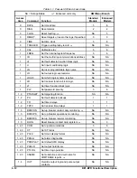
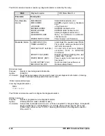
The DIAG command reads or resets any diagnostic alarms recorded by the relay.
DIAG
Diagnostic alarms
HMI Menu Branch: 2
Parameter
Description
Non-Maskable
Alarms
RAM ERROR:
Static RAM read/write error
ROM ERROR:
EPROM program memory checksum
error
uP ERROR:
uP self test error
EEPROM ERROR:
EEPROM read/write error
EEDATA ERROR:
EEPROM data checksum error
ADC ERR:
Analog to digital converter error
CALIBRATION ERR:
Relay not calibrated or calibration
checksum error
POWER SUPPLY ERR:
Power supply out of tolerance
Maskable Alarms
ALARM LOGIC (OA):
Alarm logic (OA equation) was TRUE
TIMER ALARM (TL):
Timer alarm setting exceeded (refer
toPTLOG Command)
CONTACT DUTY ALM (DL):
C o n ta c t d u ty m a x i m u m ( D M A X )
exceeded (refer to BKRCON
Command)
BKROP >1 SEC (BKR):
Breaker operation (clearing) time was
greater than 1 second
POWER RESET (RST):
Power supply to microprocessor has
been reset
CLOCK NOT SET (CLK):
Real time clock has not been set
RECLOSE FAIL (RF):
Reclose attempt failed
DIAG Command
Purpose:
Reads or resets diagnostic information.
Syntax:
DIAG[=0]
Comments:
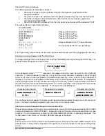
No access area password is required to read or reset diagnostic information. Entering
DIAG=0 will reset all diagnostics that can be reset.
DIAG Command Example
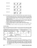
View any diagnostic alarms.
DIAG
TIMER ALARM
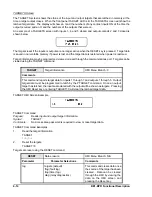
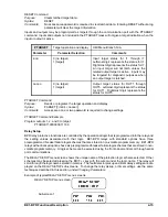
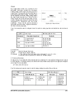
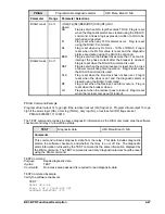
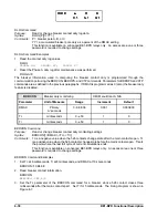
The PDIAG command is used to configure the diagnostic alarms.
PDIAG Command
Purpose:
Reads or programs service diagnostic alarms.
Syntax:
PDIAG[=<DIAG1 mask>,<DIAG2 mask>]
Comments:
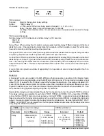
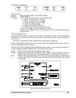
Access area level password one, two, or three is required to change settings. A diagnostic
flag is enabled by a 1 and disabled by a 0. DIAG1 drives virtual output 14 (O14) and
DIAG2 drives virtual output 15 (O15). Entering PDIAG returns the diagnostic mask for
O14 and O15.
Содержание BE1-BPR
Страница 1: ...Publication 9 2720 00 990 Revision E 12 98 INSTRUCTION MANUAL for BE1 BPR BREAKER PROTECTION RELAY...
Страница 31: ...BE1 BPR Application 2 17...
Страница 41: ...BE1 BPR Human Machine Interface 3 3 Figure 3 3 BE1 BPR Relay Horizontal Mount Front And Rear Views...
Страница 42: ...3 4 BE1 BPR Human Machine Interface Figure 3 4 BE1 BPR Relay Vertical Mount Front View...
Страница 43: ...BE1 BPR Human Machine Interface 3 5 Figure 3 5 BE1 BPR Relay Vertical Mount Rear View...
Страница 49: ...4 6 BE1 BPR Functional Description Figure 4 2 Enhanced BE1 BPR Menu Display Screens...
Страница 50: ...BE1 BPR Functional Description 4 7 Figure 4 3 Standard BE1 BPR Menu Display Screens...
Страница 94: ...5 4 BE1 BPR BESTlogic Figure 5 1 BESTlogic Function Blocks...
Страница 120: ...7 2 BE1 BPR Installation Figure 7 1 Overall Dimensions Figure 7 2 Cutout Dimensions Panel Mount...
Страница 121: ...BE1 BPR Installation 7 3 Figure 7 3 Overall Dimensions Vertical Mount...
Страница 122: ...7 4 BE1 BPR Installation Figure 7 4 Overall Dimensions Side View Vertical Mount...
Страница 123: ...BE1 BPR Installation 7 5 Figure 7 5 Panel Drilling Diagram Vertical Mount...

