


Spot coordinates can be placed on floors, walls, toposurfaces, and boundary lines. You can also place spot
coordinates on non-horizontal surfaces and non-planar edges. When you display the elevation of the selected
point in addition to the spot coordinates, you can place the spot coordinate in the same locations you can
place a spot elevation.
To place spot coordinates:
1
Click Annotate tab
➤
Dimension panel drop-down
➤
Spot Coordinate.
2
In the Type Selector, select the type of spot coordinate to place.
3
On the Options Bar, select or clear the Leader option. If the Leader option is selected, optionally
select the Shoulder option. This adds a bend to the spot elevation leader.
4
If you want the elevation to display in addition to the spot coordinates:
a
Right-click Element Properties.
b
In the Instance Properties dialog, click Edit Type.
c
Under Text, select the Include Elevation option.
5
Select an edge of an element or a point on a toposurface.
When you move the cursor over an element on which you can place the spot coordinate, the
spot coordinate value appears in the drawing area.
6
If you are placing a spot coordinate:
■
without a leader, click to place it.
■
with a leader, move the cursor away from the element, and click to place the spot coordinate.
■
with a leader and a shoulder, move the cursor away from the element. Click once to place
the leader shoulder. Move the cursor again and then click to place the spot coordinate.
7
To finish, click Modify tab
➤
Selection panel
➤
Modify.
If you select a spot coordinate after placing it, you can move it using the drag controls. If you delete an
element that is referenced or turn off its visibility, the spot coordinate is removed.
To modify the appearance of the spot elevation, select it and right-click Element Properties. For more
information, see
on page 290.
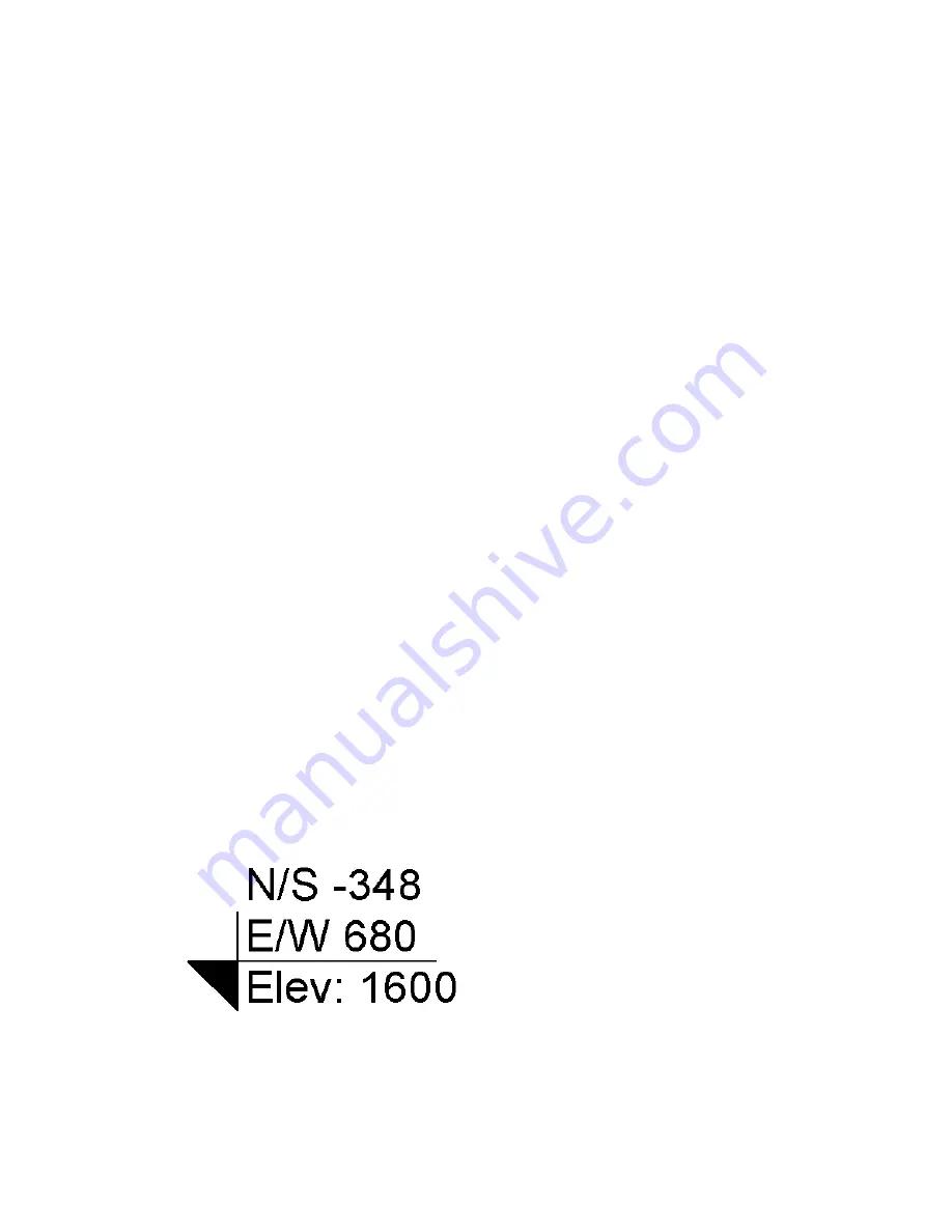
Adding Supplementary Text to Spot Coordinate Dimensions
You can add supplementary text to spot dimensions. By editing the type parameters for the spot coordinate,
you can add text for the North/South indicator, East/West indicator, and elevation indicator. This text can
appear as a suffix or a prefix to the spot coordinate values.
In addition, you can edit the instance parameters for a spot coordinate to add supplementary prefix and/or
suffix text to the top, bottom, and elevation values.
Spot Dimensions | 281
Содержание 256B1-05A761-1301 - AutoCAD Revit Structure Suite 2010
Страница 1: ...Revit Architecture 2010 User s Guide March 2009 ...
Страница 4: ......
Страница 42: ...xlii ...
Страница 84: ...42 ...
Страница 126: ...84 ...
Страница 166: ...124 ...
Страница 229: ...Schedule Field Formatting Calculating Totals Specifying Schedule Properties 187 ...
Страница 230: ...Schedule with Grid Lines Schedule with Grid Lines and an Outline 188 Chapter 5 Project Views ...
Страница 304: ...262 ...
Страница 427: ...Defining the first scale vector Defining the second scale vector Resizing Graphically 385 ...
Страница 454: ...Before painting applying material to stairs 412 Chapter 8 Editing Elements ...
Страница 456: ...414 ...
Страница 486: ...444 ...
Страница 674: ...632 ...
Страница 802: ... Attachment Style Cut Column Attachment Justification Intersect Column Midline 760 Chapter 13 Architectural Design ...
Страница 809: ...Curtain wall Curtain Grid Curtain Walls Curtain Grids and Mullions 767 ...
Страница 994: ...952 ...
Страница 1016: ...974 ...
Страница 1204: ...1162 ...
Страница 1290: ...1248 ...
Страница 1318: ...1276 ...
Страница 1372: ...1330 ...
Страница 1382: ...1340 ...
Страница 1462: ...1420 ...
Страница 1492: ...1450 ...


