


■
All properties BYLAYER, new layers for overrides
. When a Revit element with view-specific graphics is
exported, in AutoCAD the entity is placed on its own layer. This option provides by-layer control over
the exported DWG file, and preserves graphical intent. However, it increases the number of layers in the
exported DWG file.
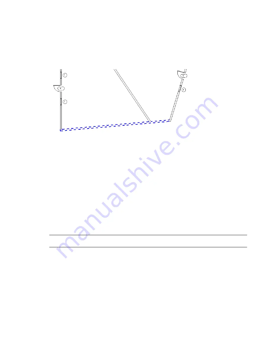
For example, suppose that, in a Revit Architecture project, most walls display with solid black lines, with a
line weight of 5. In a floor plan, however, you have changed the view-specific element graphics for one wall
to use dashed blue lines, with a line weight of 7.
When you export this view to DWG or DXF and, for Layers and Properties, select:
■
Category properties BYLAYER, overrides BYENTITY: All walls in this Revit category, including the blue
wall, are assigned to one layer in AutoCAD. The blue wall, however, retains its unique attributes (blue,
dashed, line weight = 7) because AutoCAD defines them
by entity
for that wall.
■
All properties BYLAYER, no overrides: All walls in this Revit category, including the blue wall, are assigned
to one layer in AutoCAD, and the blue wall does not retain its unique characteristics. In AutoCAD, it
looks the same as the other walls in the layer.
■
All properties BYLAYER, new layers for overrides: All walls in this Revit category, except for the blue wall,
are assigned to one layer in AutoCAD. The blue wall retains its unique attributes, but it is assigned to its
own layer.
Linetype Scaling
Select a value from the Linetype Scaling list to control the LTSCALE and PSLTSCALE settings in AutoCAD
and how linetype definitions are exported from Revit Architecture.
NOTE
You can define Linetype Scaling when exporting to DXF or DWG. This option is not available when exporting
to DGN or SAT.
Linetypes determine the particular dash-dot sequence, the relative lengths of dashes and blank spaces, and
the characteristics of any included text or shapes in lines. In Revit Architecture, these are defined by object
styles for categories (Manage tab
➤
Project Settings panel
➤
Settings drop-down
➤
Object Styles) or as
view-specific element graphics for individual elements. (See
and Graphic Display of Individual Elements
on page 199.)
1350 | Chapter 24 Interoperability
Содержание 256B1-05A761-1301 - AutoCAD Revit Structure Suite 2010
Страница 1: ...Revit Architecture 2010 User s Guide March 2009 ...
Страница 4: ......
Страница 42: ...xlii ...
Страница 84: ...42 ...
Страница 126: ...84 ...
Страница 166: ...124 ...
Страница 229: ...Schedule Field Formatting Calculating Totals Specifying Schedule Properties 187 ...
Страница 230: ...Schedule with Grid Lines Schedule with Grid Lines and an Outline 188 Chapter 5 Project Views ...
Страница 304: ...262 ...
Страница 427: ...Defining the first scale vector Defining the second scale vector Resizing Graphically 385 ...
Страница 454: ...Before painting applying material to stairs 412 Chapter 8 Editing Elements ...
Страница 456: ...414 ...
Страница 486: ...444 ...
Страница 674: ...632 ...
Страница 802: ... Attachment Style Cut Column Attachment Justification Intersect Column Midline 760 Chapter 13 Architectural Design ...
Страница 809: ...Curtain wall Curtain Grid Curtain Walls Curtain Grids and Mullions 767 ...
Страница 994: ...952 ...
Страница 1016: ...974 ...
Страница 1204: ...1162 ...
Страница 1290: ...1248 ...
Страница 1318: ...1276 ...
Страница 1372: ...1330 ...
Страница 1382: ...1340 ...
Страница 1462: ...1420 ...
Страница 1492: ...1450 ...


