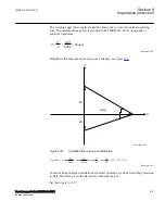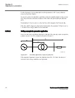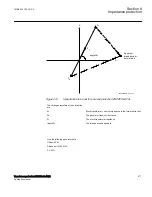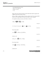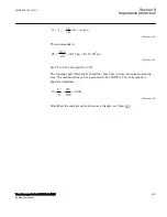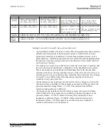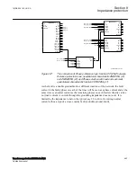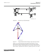
Rt = 0.0054 pu (transf. ZBase)
1-st step in
calculation
ZBase = 0.9522 Ω (generator)
Xd' = 0.2960 · 0.952 = 0.282 Ω
Rs = 0.0029 · 0.952 = 0.003 Ω
ZBase (13.8 kV) = 0.6348 Ω
Xt = 0.100 · 0.6348 = 0.064 Ω
Rt = 0.0054 · 0.635 = 0.003 Ω
Xline = 300 · 0.4289 = 128.7 Ω
Rline = 300 · 0.0659 = 19.8 Ω
(X and R above on 230 kV basis)
Xe = Z
e
· sin (φ) = 10.52 Ω
Re = Z
e
· cos (φ) = 1.05 Ω
(Xe and Re on 230 kV basis)
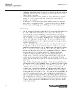
2-nd step in
calculation
Xd' = 0.2960 · 0.952 = 0.282 Ω
Rs = 0.0029 · 0.952 = 0.003 Ω
Xt = 0.100 · 0.6348 = 0.064 Ω
Rt = 0.0054 · 0.635 = 0.003 Ω
Xline= 128.7 · (13.8/230)
2
= 0.463
Ω
Rline = 19.8 · (13.8/230)
2
= 0.071
Ω
(X and R referred to 13.8 kV)
Xe = 10.52 · (13.8/230)
2
= 0.038
Ω
Re = 1.05 · (13.8/230)
2
= 0.004 Ω
(X and R referred to 13.8 kV)
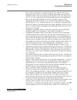
3-rd step in
calculation
ForwardX = Xt + Xline + Xe = 0.064 + 0.463 + 0.038 = 0.565 Ω; ReverseX = Xd' = 0.282 Ω (all referred to gen. voltage 13.8 kV)
ForwardR = Rt + Rline + Re = 0.003 + 0.071 + 0.004 = 0.078 Ω; ReverseR = Rs = 0.003 Ω (all referred to gen. voltage 13.8 kV)
Final
resulted
settings
ForwardX = 0.565/0.9522 · 100 = 59.33 in % ZBase; ReverseX = 0.282/0.9522 · 100 = 29.6 in % ZBase (all referred to 13.8 kV)
ForwardR = 0.078/0.9522 · 100 = 8.19 in % ZBase; ReverseR = 0.003/0.9522 · 100 = 0.29 in % ZBase (all referred to 13.8 kV)
Settings
ForwardR
,
ForwardX
,
ReverseR
, and
ReverseX
.
•
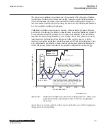
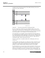
A precondition in order to be able to use the Out-of-step protection and construct a
suitable lens characteristic is that the power system in which the Out-of-step
protection is installed, is modeled as a two-machine equivalent system, or as a
single machine – infinite bus equivalent power system. Then the impedances from
the position of the Out-of-step protection in the direction of the normal load flow
can be taken as forward.
•
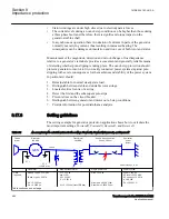
The settings
ForwardX
,
ForwardR
,
ReverseX
and
ReverseR
must, if possible, take
into account, the post-disturbance configuration of the simplified power system.
This is not always easy, in particular with islanding. But for the two machine
model as in Table
, the most probable scenario is that only one line is in service
after the fault on one power line has been cleared by line protections. The settings
ForwardX
,
ForwardR
must therefore take into account the reactance and
resistance of only one power line.
•
All the reactances and resistances must be referred to the voltage level where the
Out-of-step relay is installed; for the example case shown in Table
generator nominal voltage VBase = 13.8 kV. This affects all the forward
reactances and resistances in Table
.
•
All reactances and resistances must be finally expressed in percent of ZBase,
where ZBase is for the example shown in Table
generator, ZBase = 0.9522 Ω. Observe that the power transformer’s base
impedance is different, ZBase = 0.6348 Ω. Observe that this latter power
transformer ZBase = 0.6348 Ω must be used when the power transformer
reactance and resistance are transformed.
1MRK 504 163-UUS A
Section 8
Impedance protection
Transformer protection RET670 2.2 ANSI
485
Application manual
Содержание RELION RET670
Страница 1: ...RELION 670 SERIES Transformer protection RET670 Version 2 2 ANSI Application manual ...
Страница 2: ......
Страница 48: ...42 ...
Страница 64: ...58 ...
Страница 74: ...68 ...
Страница 104: ...98 ...
Страница 194: ...188 ...
Страница 518: ...512 ...
Страница 618: ...612 ...
Страница 648: ...642 ...
Страница 666: ...660 ...
Страница 672: ...666 ...
Страница 682: ...676 ...
Страница 844: ...838 ...
Страница 868: ...862 ...
Страница 956: ...950 ...
Страница 964: ...958 ...
Страница 1004: ...998 ...
Страница 1014: ...1008 ...
Страница 1015: ...1009 ...


