


•
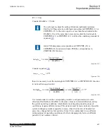
They must generally be blocked during normal operation and released during
power swings.
•
Their operation must be time delayed but shorter (with sufficient margin) than the
set time delay of normal distance protection zone 2, which is generally blocked by
the power swing.
•
Their resistive reach setting must secure, together with the set time delay for their
operation, that the slowest expected swings pass the impedance operate area
without initiating their operation.
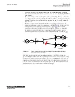
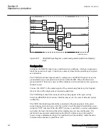
Communication and tripping logic as used by the power swing distance protection
zones is schematically presented in figure
The operation of the power swing zones is conditioned by the operation of Power
swing detection (ZMRPSB, 68) function. They operate in PUTT or POTT
communication scheme with corresponding distance protection zones at the remote line
end. It is preferred to use the communication channels over the optionally available
“Line Data Communication Module - LDCM” and the “Binary signal transfer to
remote end” function. It is also possible to include, in an easy way (by means of
configuration possibilities), the complete functionality into regular scheme
communication logic for the distance protection function. The communication scheme
for the regular distance protection does not operate during the power-swing conditions,
because the distance protection zones included in the scheme are normally blocked.
The powerswing zones can for this reason use the same communication facilities
during the power-swing conditions.
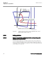
Only one power swing zone is necessary in distance protection at each line terminal, if
the POTT communication scheme is applied. One underreaching power swing zone,
which sends the time delayed carrier signal, and one overreaching power swing zone,
which performs the local tripping condition, are necessary with PUTT schemes.
The operation of the distance protection zones with long time delay (for example, zone
3) is in many cases not blocked by the power swing detection elements. This allows in
such cases the distance protection zone 3 (together with the full-scheme design of the
distance protection function) to be used at the same time as the overreaching power-
swing zone.
1MRK 504 163-UUS A
Section 8
Impedance protection
Transformer protection RET670 2.2 ANSI
461
Application manual
Содержание RELION RET670
Страница 1: ...RELION 670 SERIES Transformer protection RET670 Version 2 2 ANSI Application manual ...
Страница 2: ......
Страница 48: ...42 ...
Страница 64: ...58 ...
Страница 74: ...68 ...
Страница 104: ...98 ...
Страница 194: ...188 ...
Страница 518: ...512 ...
Страница 618: ...612 ...
Страница 648: ...642 ...
Страница 666: ...660 ...
Страница 672: ...666 ...
Страница 682: ...676 ...
Страница 844: ...838 ...
Страница 868: ...862 ...
Страница 956: ...950 ...
Страница 964: ...958 ...
Страница 1004: ...998 ...
Страница 1014: ...1008 ...
Страница 1015: ...1009 ...


