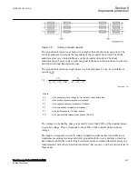


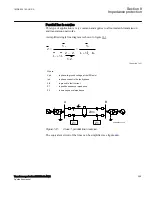

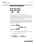


For this example with a fault between T and B, the measured impedance from the T
point to the fault will be increased by a factor defined as the sum of the currents from T
point to the fault divided by the IED current. For the IED at C, the impedance on the
high voltage side U1 has to be transferred to the measuring voltage level by the
transformer ratio.
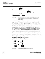
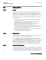
Another complication that might occur depending on the topology is that the current
from one end can have a reverse direction for fault on the protected line. For example
for faults at T the current from B might go in reverse direction from B to C depending
on the system parameters (see the dotted line in figure
), given that the distance
protection in B to T will measure wrong direction.
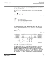
In three-end application, depending on the source impedance behind the IEDs, the
impedances of the protected object and the fault location, it might be necessary to
accept zone2 trip in one end or sequential trip in one end.
Generally for this type of application it is difficult to select settings of zone1 that both
gives overlapping of the zones with enough sensitivity without interference with other
zone1 settings that is, without selectivity conflicts. Careful fault calculations are
necessary to determine suitable settings and selection of proper scheme
communication.
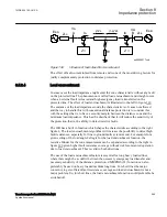
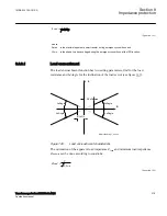
Fault resistance
SEMOD154680-288 v2
The performance of distance protection for single phase-to-ground faults is very
important, because normally more than 70% of the faults on transmission lines are
single phase-to-ground faults. At these faults, the fault resistance is composed of three
parts: arc resistance, resistance of a tower construction, and tower-footing resistance.
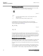
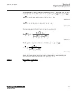
The arc resistance can be calculated according to Warrington's formula:
1.4
28707 L
Rarc
I
×
=
EQUATION1456 V1 EN-US
(Equation 175)
where:
L
represents the length of the arc (in meters). This equation applies for the distance protection zone
1. Consider approximately three-times arc foot spacing for the zone 2 and wind speed of
approximately 50 km/h
I
is the actual fault current in A.
In practice, the setting of fault resistance for both phase-to-ground (
RFPE
) and phase-
to-phase (
RFPP
) should be as high as possible without interfering with the load
impedance in order to obtain reliable fault detection.
1MRK 504 163-UUS A
Section 8
Impedance protection
Transformer protection RET670 2.2 ANSI
305
Application manual
Содержание RELION RET670
Страница 1: ...RELION 670 SERIES Transformer protection RET670 Version 2 2 ANSI Application manual ...
Страница 2: ......
Страница 48: ...42 ...
Страница 64: ...58 ...
Страница 74: ...68 ...
Страница 104: ...98 ...
Страница 194: ...188 ...
Страница 518: ...512 ...
Страница 618: ...612 ...
Страница 648: ...642 ...
Страница 666: ...660 ...
Страница 672: ...666 ...
Страница 682: ...676 ...
Страница 844: ...838 ...
Страница 868: ...862 ...
Страница 956: ...950 ...
Страница 964: ...958 ...
Страница 1004: ...998 ...
Страница 1014: ...1008 ...
Страница 1015: ...1009 ...


