


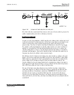


voltage (3U0) will have the same magnitude in different places in the network due to
low voltage drop distribution.
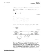
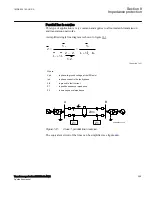
The magnitude of the total fault current can be calculated according to the formula
below:
(
)
2
2
R
L
C
0
3I
I
I
I
=
+
-
EQUATION1271 V3 EN-US
(Equation 160)
Where:
3I0
is the ground-fault current (A)
IR
is the current through the neutral point resistor (A)
IL
is the current through the neutral point reactor (A)
IC
is the total capacitive ground-fault current (A)
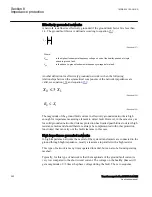
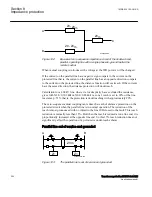
The neutral point reactor is normally designed so that it can be tuned to a position
where the reactive current balances the capacitive current from the network that is:
1
3
L
C
w
w
=
× ×
EQUATION1272 V1 EN-US
(Equation 161)
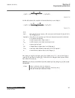
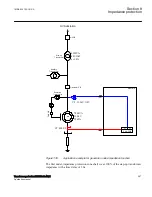
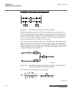
IEC05000216 V2 EN-US
Figure 138:
High impedance grounding network
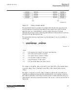
The operation of high impedance grounded networks is different compare to solid
grounded networks where all major faults have to be cleared very fast. In high
impedance grounded networks, some system operators do not clear single phase-to-
ground faults immediately; they clear the line later when it is more convenient. In case
of cross country faults, many network operators want to selectively clear one of the
two ground-faults. To handle this type phenomena a separate function called Phase
1MRK 504 163-UUS A
Section 8
Impedance protection
Transformer protection RET670 2.2 ANSI
293
Application manual
Содержание RELION RET670
Страница 1: ...RELION 670 SERIES Transformer protection RET670 Version 2 2 ANSI Application manual ...
Страница 2: ......
Страница 48: ...42 ...
Страница 64: ...58 ...
Страница 74: ...68 ...
Страница 104: ...98 ...
Страница 194: ...188 ...
Страница 518: ...512 ...
Страница 618: ...612 ...
Страница 648: ...642 ...
Страница 666: ...660 ...
Страница 672: ...666 ...
Страница 682: ...676 ...
Страница 844: ...838 ...
Страница 868: ...862 ...
Страница 956: ...950 ...
Страница 964: ...958 ...
Страница 1004: ...998 ...
Страница 1014: ...1008 ...
Страница 1015: ...1009 ...


