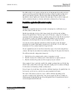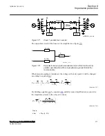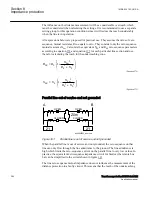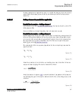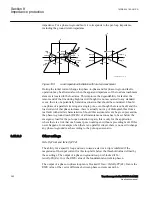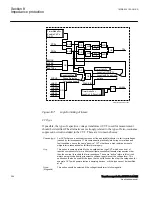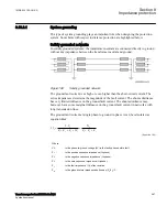
Setting of the resistive reach for the underreaching zone 1 should follow the condition
to minimize the risk for overreaching:
RFPG
4.5 X1
£
×
ANSIEQUATION2305 V1 EN-US
(Equation 295)
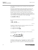
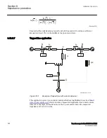
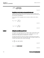
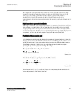
The fault resistance for phase-to-phase faults is normally quite low compared to the
fault resistance for phase-to-ground faults. To minimize the risk for overreaching, limit
the setting of the zone1 reach in the resistive direction for phase-to-phase loop
measurement based on equation
.
6
1
RFPPZx
X Zx
IECEQUATION2306 V3 EN-US
(Equation 296)
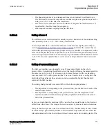
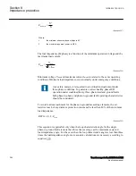
The setting
XLd
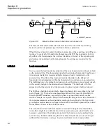
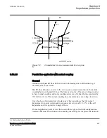
is primarily there to define the border between what is considered a
fault and what is just normal operation. See figure
examples of normal operation are reactive load from reactive power compensation
equipment or the capacitive charging of a long high-voltage power line.
XLd
needs to
be set with some margin towards normal apparent reactance; not more than 90% of the
said reactance or just as much as is needed from a zone reach point of view.
As with the settings
RLdFwd
and
RldRev
,
XLd
is representing a per-phase load
impedance of a symmetrical star-coupled representation. For a symmetrical load or
three-phase and phase-to-phase faults, this means per-phase, or positive-sequence,
impedance. During a phase-to-earth fault, it means the per-loop impedance, including
the earth return impedance.
8.12.3.7
Zone reach setting lower than minimum load impedance
GUID-68C336F4-5285-4167-B3F8-B0963BD85439 v5
Even if the resistive reach of all protection zones is set lower than the lowest expected
load impedance and there is no risk for load encroachment, it is still necessary to set
RLdFwd
,
RldRev
and
LdAngle
according to the expected load situation, since these
settings are used internally in the function as reference points to improve the
performance of the phase selection.
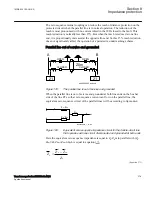
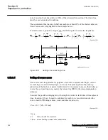
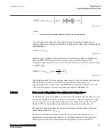
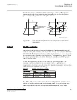
The maximum permissible resistive reach for any zone must be checked to ensure that
there is a sufficient setting margin between the boundary and the minimum load
impedance. The minimum load impedance (Ω/phase) is calculated with equation
.
1MRK 504 163-UUS A
Section 8
Impedance protection
Transformer protection RET670 2.2 ANSI
389
Application manual
Содержание RELION RET670
Страница 1: ...RELION 670 SERIES Transformer protection RET670 Version 2 2 ANSI Application manual ...
Страница 2: ......
Страница 48: ...42 ...
Страница 64: ...58 ...
Страница 74: ...68 ...
Страница 104: ...98 ...
Страница 194: ...188 ...
Страница 518: ...512 ...
Страница 618: ...612 ...
Страница 648: ...642 ...
Страница 666: ...660 ...
Страница 672: ...666 ...
Страница 682: ...676 ...
Страница 844: ...838 ...
Страница 868: ...862 ...
Страница 956: ...950 ...
Страница 964: ...958 ...
Страница 1004: ...998 ...
Страница 1014: ...1008 ...
Страница 1015: ...1009 ...

