
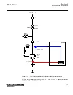
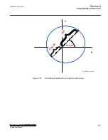


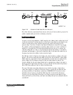

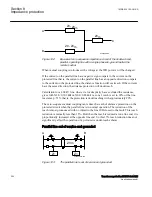


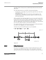


Parallel line in service
SEMOD154680-175 v2
This type of application is very common and applies to all normal sub-transmission
and transmission networks.
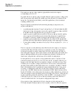
A simplified single line diagram is shown in figure
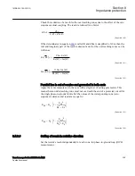
ph
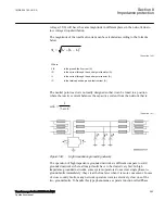
ph
0
1
ph
N
ph
0
1
0
V
V
Z
Z
I
3
K
I
3I
3 Z
I
Z
=
=
-
+
×
+
×
×
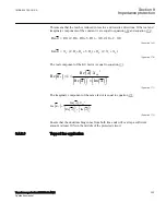
EQUATION1275 V3 EN-US
(Equation 164)
Where:
Vph
is phase-to-ground voltage at the IED point
Iph
is phase current in the faulty phase
3I0
is ground to fault current
Z1
is positive sequence impedance
Z0
is zero sequence impedance
Z0m
A
B
Z<
Z<
en05000221.vsd
IEC05000221 V1 EN-US
Figure 141:
Class 1, parallel line in service.
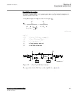
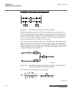
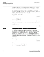
The equivalent circuit of the lines can be simplified, see figure
.
1MRK 504 163-UUS A
Section 8
Impedance protection
Transformer protection RET670 2.2 ANSI
299
Application manual
Содержание RELION RET670
Страница 1: ...RELION 670 SERIES Transformer protection RET670 Version 2 2 ANSI Application manual ...
Страница 2: ......
Страница 48: ...42 ...
Страница 64: ...58 ...
Страница 74: ...68 ...
Страница 104: ...98 ...
Страница 194: ...188 ...
Страница 518: ...512 ...
Страница 618: ...612 ...
Страница 648: ...642 ...
Страница 666: ...660 ...
Страница 672: ...666 ...
Страница 682: ...676 ...
Страница 844: ...838 ...
Страница 868: ...862 ...
Страница 956: ...950 ...
Страница 964: ...958 ...
Страница 1004: ...998 ...
Страница 1014: ...1008 ...
Страница 1015: ...1009 ...