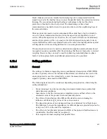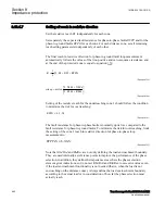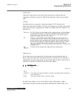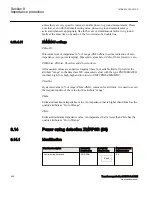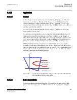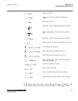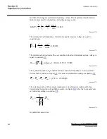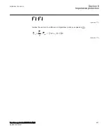
The increased reach related to the one used in non compensated system is
recommended for all protections in the vicinity of series capacitors to compensate for
delay in the operation caused by the sub harmonic swinging.
Settings of the resistive reaches are limited according to the minimum load impedance.
Reverse zone
GUID-BDDB2E91-3E37-4F78-99C2-8A9C3E3B275B v2
The reverse zone that is normally used in the communication schemes for functions
like fault current reversal logic, weak-in-feed logic or issuing carrier send in blocking
scheme must detect all faults in the reverse direction which is detected in the opposite
IED by the overreaching zone 2. The maximum reach for the protection in the opposite
IED can be achieved with the series capacitor in operation.
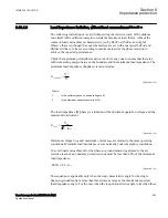
The reactive reach can be set according to the following formula: X1=1.3·
(X1
2Rem
-0.5(X1
L
-X
C
))
Settings of the resistive reaches are according to the minimum load impedance:
Optional higher distance protection zones
GUID-506F93E2-1E1C-4EEC-B260-F362F3897C4F v1
When some additional distance protection zones (zone 4, for example) are used they
must be set according to the influence of the series capacitor.
8.13.4.6
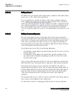
Setting of zones for parallel line application
GUID-E1228762-EBF7-4E58-9A52-96C5D22A0F0D v1
Parallel line in service – Setting of zone 1
GUID-1EDD265C-43D4-4D1A-A9DC-830E18B3267C v1
With reference to section
, the zone reach can be set to 85%
of the protected line.
However, influence of mutual impedance has to be taken into account.
Parallel line in service – setting of zone 2
GUID-0985014F-B0CB-4872-8644-F87B34973B1F v1
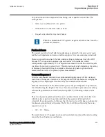
Overreaching zones (in general, zones 2 and 3) must overreach the protected circuit in
all cases. The greatest reduction of a reach occurs in cases when both parallel circuits
are in service with a single phase-to-ground fault located at the end of a protected line.
The equivalent zero sequence impedance circuit for this case is equal to the one in
figure
.
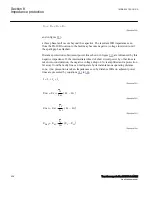
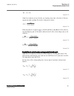
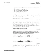
The components of the zero sequence impedance for the overreaching zones must be
equal to at least:
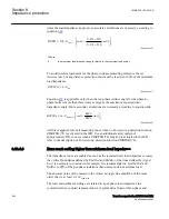
R
0E
R
0
R
m0
+
=
EQUATION553 V1 EN-US
(Equation 352)
Section 8
1MRK 504 163-UUS A
Impedance protection
440
Transformer protection RET670 2.2 ANSI
Application manual
Содержание RELION RET670
Страница 1: ...RELION 670 SERIES Transformer protection RET670 Version 2 2 ANSI Application manual ...
Страница 2: ......
Страница 48: ...42 ...
Страница 64: ...58 ...
Страница 74: ...68 ...
Страница 104: ...98 ...
Страница 194: ...188 ...
Страница 518: ...512 ...
Страница 618: ...612 ...
Страница 648: ...642 ...
Страница 666: ...660 ...
Страница 672: ...666 ...
Страница 682: ...676 ...
Страница 844: ...838 ...
Страница 868: ...862 ...
Страница 956: ...950 ...
Страница 964: ...958 ...
Страница 1004: ...998 ...
Страница 1014: ...1008 ...
Страница 1015: ...1009 ...

