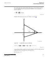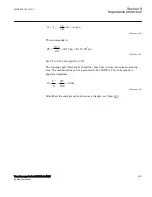
•
Stator windings are under high stress due to electrodynamic forces.
•
The current levels during an out-of-step condition can be higher than those during
a three-phase fault and, therefore, there is significant torque impact on the
generator-turbine shaft.
•
In asynchronous operation there is induction of currents in parts of the generator
normally not carrying current, thus resulting in increased heating. The
consequence can be damages on insulation and iron core of both rotor and stator.
Measurement of the magnitude, direction and rate-of-change of load impedance
relative to a generator’s terminals provides a convenient and generally reliable means
of detecting whether pole-slipping is taking place. The out-of-step protection should
protect a generator or motor (or two weakly connected power systems) against pole-
slipping with severe consequences for the machines and stability of the power system.
In particular it should:
1. Remain stable for normal steady state load.
2. Distinguish between stable and unstable rotor swings.
3. Locate electrical centre of a swing.
4. Detect the first and the subsequent pole-slips.
5. Prevent stress on the circuit breaker.
6. Distinguish between generator and motor out-of-step conditions.
7. Provide information for post-disturbance analysis.
8.17.3
Setting guidelines
GUID-CB86FCF6-8718-40BE-BDF2-028C24AB367D v6
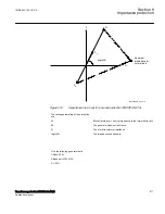
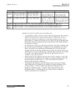
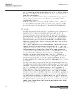
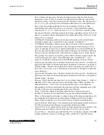
The setting example for generator protection application shows how to calculate the
most important settings
ForwardR
,
ForwardX
,
ReverseR
, and
ReverseX
.
Table 36:
An example how to calculate values for the settings ForwardR, ForwardX, ReverseR, and ReverseX
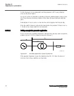
GEN
Turbine
(hydro)
Generator
200 MVA
Transformer
300 MVA
Double circuit power line
230 kV, 300 km
Equivalent
power
system
CT 1
CT 2
to OOS relay
13.8 kV
ANSI11000090_2_en.vsd
Y
ANSI11000090 V2 EN-US
Generator
Step-up transformer
Single power line
Power system
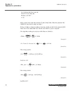
Data
required
VBase = Vgen = 13.8 kV
IBase = Igen = 8367 A
Xd' = 0.2960 pu
Rs = 0.0029 pu
V1 = 13.8 kV
usc = 10%
V2 = 230 kV
I1 = 12 551 A
Xt = 0.1000 pu (transf. ZBase)
Vline = 230 kV
Xline/km = 0.4289 Ω/km
Rline/km = 0.0659 Ω/km
Vnom = 230 kV
SC level = 5000 MVA
SC current = 12 551 A
φ = 84.289°
Ze = 10.5801 Ω
Table continues on next page
Section 8
1MRK 504 163-UUS A
Impedance protection
484
Transformer protection RET670 2.2 ANSI
Application manual
Содержание RELION RET670
Страница 1: ...RELION 670 SERIES Transformer protection RET670 Version 2 2 ANSI Application manual ...
Страница 2: ......
Страница 48: ...42 ...
Страница 64: ...58 ...
Страница 74: ...68 ...
Страница 104: ...98 ...
Страница 194: ...188 ...
Страница 518: ...512 ...
Страница 618: ...612 ...
Страница 648: ...642 ...
Страница 666: ...660 ...
Страница 672: ...666 ...
Страница 682: ...676 ...
Страница 844: ...838 ...
Страница 868: ...862 ...
Страница 956: ...950 ...
Страница 964: ...958 ...
Страница 1004: ...998 ...
Страница 1014: ...1008 ...
Страница 1015: ...1009 ...


