


4 - 87
ENG
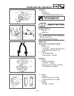
ENGINE REMOVAL
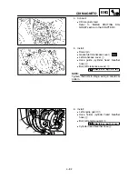
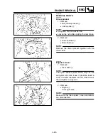
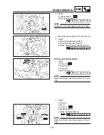
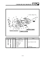
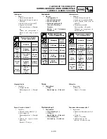
2. Install:
●
Lock washer
1
●
Nut (drive sprocket)
2
NOTE:
Tighten the nut while applying the rear brake.
T
R
.
.
75 Nm (7.5 m · kg, 54 ft · lb)
3. Bend the lock washer tab to lock the nut.
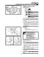
4. Install:
●
Drive chain sprocket guide
1
●
Drive chain sprocket cover
2
●
Screw (drive chain sprocket cover)
3
T
R
.
.
8 Nm (0.8 m · kg, 5.8 ft · lb)
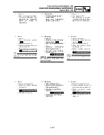
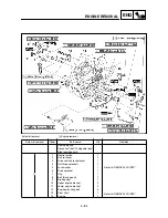
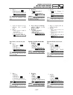
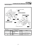
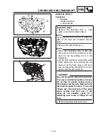
Oil hose and neutral switch
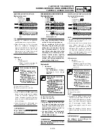
1. Install:
●
O-ring
1
●
Dowel pin
2
●
Oil hose
3
●
Bolt (oil hose)
4
NOTE:
Apply the lithium soap base grease on the O-
ring.
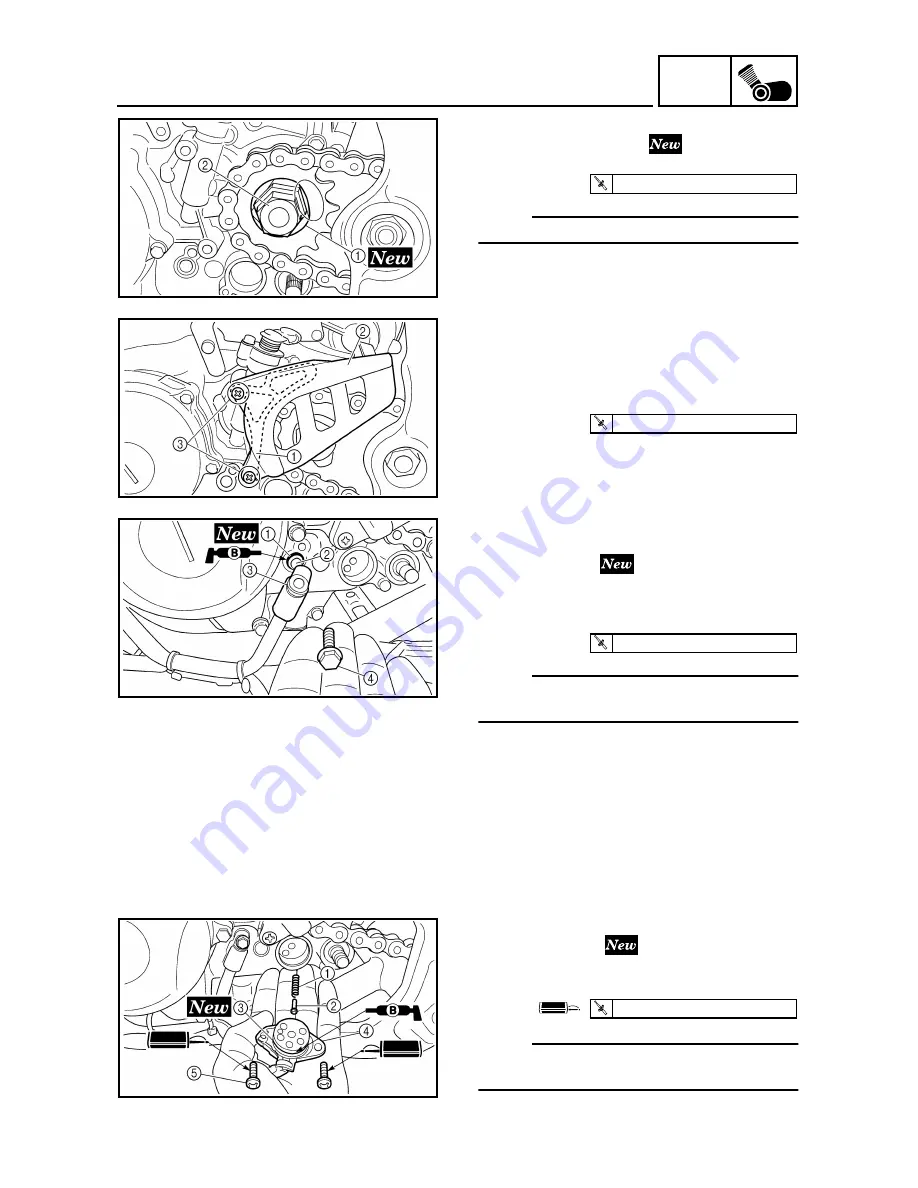
2. Install:
●
Spring
1
●
Pin
2
●
O-ring
3
●
Neutral switch
4
●
Screw (neutral switch)
5
NOTE:
Apply the lithium soap base grease on the O-
ring.
T
R
.
.
10 Nm (1.0 m · kg, 7.2 ft · lb)
T
R
.
.
4 Nm (0.4 m · kg, 2.9 ft · lb)
Summary of Contents for WR250F(P)
Page 604: ...5 67 CHAS REAR SHOCK ABSORBER 8 Install Band 1 Taillight connector 2...
Page 692: ......
Page 693: ......


