2 - 20
SPEC
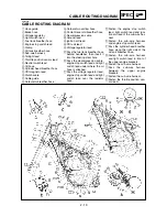
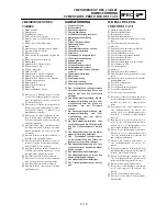
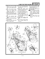
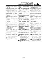
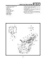
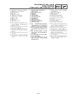
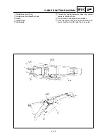
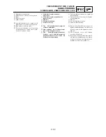
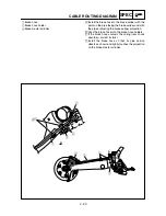
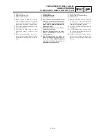
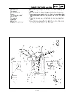
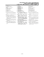
CABLE ROUTING DIAGRAM
Ò
Make sure that the throttle
position sensor lead coupler
does not go outside the chas-
sis.
˜
Pass the carburetor breather
hoses and overflow hose
between the connecting rod
and cross tube (frame).
ˆ
Fasten the neutral switch lead
on the oil hose with a plastic
locking tie and cut off the tie
end.
Ø
Pass the cylinder head
breather hose through the hose
guide.
∏
Pass the clutch cable through
the cable guide.
Œ
Fasten the neutral switch lead
and CDI magneto lead.
Â
Pass the clutch cable along the
inner side of the cylinder head
breather hose.
Í
Pass the cylinder head
breather hose along the inner
side of the radiator hose.
Ê
Pass the clutch cable in front of
the radiator mounting boss.
Ë
Fit the brake hose into the
guides on the protector.
◊
Pass the neutral switch lead
and CDI magneto lead through
the cable guide.
„
Fasten the ground lead
together with the ignition coil
lead.
Ù
Do not allow the light switch
lead to slacken between the
two clamps.
Á
Pass the decompression cable
along the right side of the cylin-
der head breather hose.
Û
Pass the clutch cable through
the cable guides.
Pass the carburetor breather
hoses, overflow hose and
coolant reservoir breather
hose so that all there hoses
do not contact the rear shock
absorber.
Position each lead at the
lower left of the main tube
(frame).
A A
A B
Summary of Contents for WR250F(P)
Page 604: ...5 67 CHAS REAR SHOCK ABSORBER 8 Install Band 1 Taillight connector 2...
Page 692: ......
Page 693: ......

