3 - 23
INSP
ADJ
VALVE CLEARANCE INSPECTION AND ADJUSTMENT
●
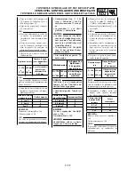
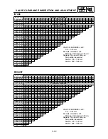
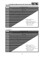
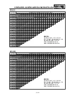
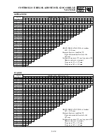
Locate the rounded-off value and the
measured valve clearance in the chart
“PAD SELECTION TABLE”. The field
where these two coordinates intersect
shows the new pad number to use.
NOTE:
Use the new pad number only as a guide
when verifying the valve clearance adjust-
ment.
●
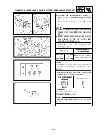
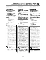
Install the new pads
7
and the valve lift-
ers
8
.
NOTE:
●
Apply the engine oil on the valve lifters.
●
Apply the molybdenum disulfied oil on the
valve stem ends.
●
Valve lifter must turn smoothly when
rotated with a finger.
●
Be careful to reinstall valve lifters and
pads in their original place.
●
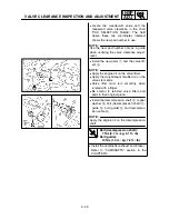
Install the decompression shaft
9
, copper
washer
0
, bolt (decompression shaft)
A
,
guide
B
, bolt (guide)
C
and decompres-
sion cable
D
.
NOTE:
Apply the engine oil on the decompression
shaft.
T
R
.
.
Bolt (decompression shaft):
7 Nm (0.7 m • kg, 5.1 ft • lb)
Bolt (guide):
10 Nm (1.0 m • kg, 7.2 ft • lb)
●
Install the camshafts (exhaust and intake).
Refer to “CAMSHAFTS” section in the
CHAPTER 4.
Summary of Contents for WR250F(P)
Page 604: ...5 67 CHAS REAR SHOCK ABSORBER 8 Install Band 1 Taillight connector 2...
Page 692: ......
Page 693: ......


