clk
cmd
CMD1
RESP
CMD2
RESP
CMD3
RESP
S
010
E
512 Bytes
+ CRC
S
512 Bytes
+ CRC
S
E
dat0
t1
50ms max
1 sec. max
t2
t3
t4
t5 t6
Min. 8 48 clocks = 56 clocks required
from CMD signal high to next MMC command.
Boot Terminated
E
clk
cmd
CMD0*
CMD0/reset
CMD1
RESP
CMD2
RESP
CMD3
RESP
S
010
E
512 Bytes
+ CRC
S
512 Bytes
+ CRC
S
E
dat0
Min. 74 clocks
required after
power is stable
to start boot
command.
t1
50ms max
1 sec. max
t2
t3
t4
t5 t6
* Refer to MMC Specification for correct argument.
E
Functional Description
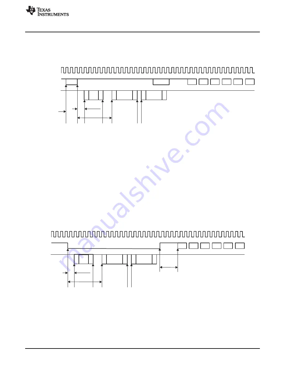
18.3.9.5 Boot Acknowledge Timeout
shows DCRC event condition asserted when there is boot acknowledge timeout and CMD0
is used.
Figure 18-25. Boot Acknowledge Timeout When Using CMD0
t1 - Data timeout counter is loaded and starts after CMD0.
t2 - Data timeout counter stops and if it is 0, SD_STAT[21] DCRC is generated.
t3 - Data timeout counter is loaded and starts.
t4 - Data timeout counter stops and if it is 0, SD_STAT[21] DCRC is generated.
t5 - Data timeout counter is loaded and starts after Data + CRC transmission.
t6 - Data timeout counter stops and if it is 0, SD_STAT[21] DCRC is generated.
shows DCRC event condition asserted when there is boot acknowledge timeout and CMD
line is held low.
Figure 18-26. Boot Acknowledge Timeout When CMD Held Low
t1 - Data timeout counter is loaded and starts after cmd line is tied to 0.
t2 - Data timeout counter stops and if it is 0, SD_STAT[21] DCRC is generated.
t3 - Data timeout counter is loaded and starts.
t4 - Data timeout counter stops and if it is 0, SD_STAT[21] DCRC is generated.
t5 - Data timeout counter is loaded and starts after Data + CRC transmission.
3373
SPRUH73H – October 2011 – Revised April 2013
Multimedia Card (MMC)
Copyright © 2011–2013, Texas Instruments Incorporated


