Installation and Reference Manual
Installing a System
Installation and Reference Manual v3.2/0410/6
21
Installing a System
A 5100 or 5108 Call Server or 4100 Call Server or 4140 Remote Call Server should be the first module to be
powered up; all subsequent modules will join this system.
1
Power up the Call Server using the power supply provided.
2
On the 5100 and 5108 Call Servers the Disk Drive LED will flash to indicate a system check, and on
the 4100 and 4140 Call Servers the NET LED will flash to indicate a system check.
3
The Call Server’s IP address will be 192.168.0.1
4
The Call Server will search for a DHCP Server, if not found, the DHCP server functionality will be
enabled. If the Call Server is connected to a network during power up and finds a DHCP Server its
internal DHCP facility will be disabled.
5
This Call Server will become the Primary Call Server.
6
The SpliceCom LED will become solid when the unit is ready.
Please note : If a Call Server is connected to a network during power up and it detects that another Call
Server exists on the network it will attempt to join this system. Ensure the Call Server is disconnected
from the network during power up if this is not required. (Please refer to Connecting Multiple Call
Servers from page 72 for further details.)
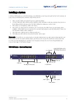
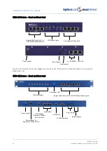
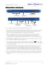
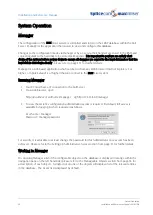
5100 Call Server – Front and Rear view
Input Triggers
Relay sockets
Power socket
Relay sockets
Integral LAN Switch with 4 x
10/100 Mbps Ethernet ports
16 analogue Phone ports
SpliceCom LED
LAN Link
2 x ISDN PRI
4 x ISDN BRI
Disk Drive LED
USB Port

