Project Planning Manual
SIPART DR20
S34
0
2
1
3
4
RB
RC
SES
MuSt
H
0
1
BA
S35
y'
y
A
y
R
/y
N
y
H
y
S
H
+
+
-
H
S31
0
2
1
y
Bl + DDC
Si
+
-
S32
0
1
t
A
t
E
-
∆
y
y
+
∆
y
S33
S21
0 0
DDC = RC = INT
∗
CB
y
S
> 50%
y
S
< 50%
T
Y
1
0
with S
1
=
9
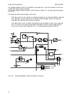
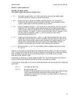
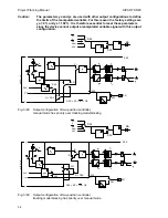
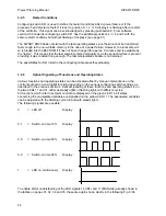
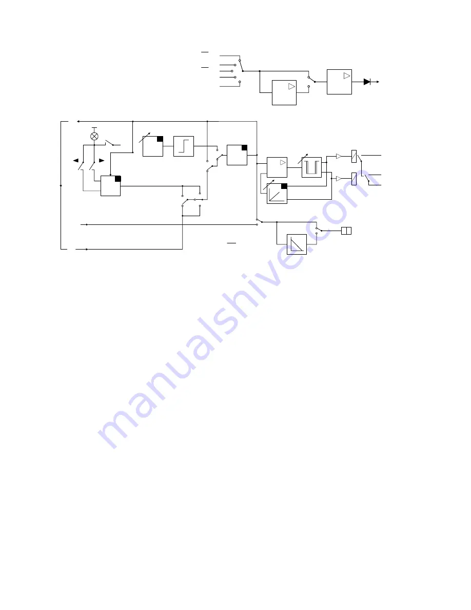
Fig. 3/31
Output configuration of three-position step controller with internal position feedback,
blocking has priority over manual mode
•
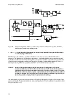
S2 = 3
S three-position step output for motor-driven actuators with external position
feedback (Figs. 3/32, 3/33)
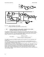
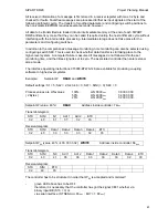
With this type of controller, a position controller is connected in series with the PID control
algorithm. The setpoint for this position controller is y, the actual value is the signal yR feed back
by the final control element. Thus limiting of the manipulated variable is possible using parameters
ya and ye and an absolute value can be entered for the safety manipulated variable yS. DDC or
tracking mode via yES is also possible with S42 = 2. P controls are also possible.
Caution: Since the external feedback circuit must never be interrupted, it is highly
recommendable to provide the final control element with an electronic position
transmitter and to feed the feedback path with a current signal of 0 or 4 to 20 mA.
If the final control element only has a potentiometer as the position transmitter, it
is better to operate the controller with internal position feedback only and only to
derive the position display from the potentiometer setting.
The parameters ta and te are also used with this output configuration to adjust the minimum pulse
pause and length. These parameters are also used together with Ty to optimize the position control
loop (see section 7.2.3).
56

