Project Planning Manual
SIPART DR20
12. Planning
Examples
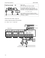
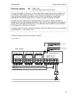
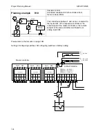
Common application / connection circuits of the SIPART DR20 controllers are shown below in the
form of planning examples. The circuits are divided according to their output configuration S, K
or Z. All input and output circuits are shown as well as the order numbers of the controllers or
additional modules required in each case. A basic circuit diagram of the control loop and a short
description facilitate understanding.
The simple applications have been intentionally shown in great detail to provide assistance to
technicians who are only occasionally required to design such circuits.
As shown, the power supply should be fused and provided with a switch; switches and fuses do
not belong to the scope of delivery of the controllers. The protective earth conductor must be
connected. The permissible power supply range and controller type are defined.
•
Power supply
As shown, the power supply should be fused and provided with a switch; switches and fuses do
not belong to the scope of delivery of the controllers. The protective earth conductor must be
connected. The permissible power supply range and controller type are defined.
•
Alarm signalling
A module for external signalling of alarms is included in all examples. This module can be omitted
if external signalling is not required. A connection circuit for the alarm module is not shown since
this differs from case to case.
The relay module must only be connected to low-voltages (see page 68).
•
Input circuits
All possible input circuits are shown. Please note in the case of a power supply to a two-wire
transmitter from the SIPART DR20 and simultaneous use of the analog inputs AE1 / AE2 that the
supply voltage for the transmitter may be only DC 15 V in an unfavourable case (see page 73).
•
Output circuits
The output circuits are shown uniformly: with K standard controllers (6DR2004) for a load-
independent current signal of 0 or 4 to 20 mA, with S standard controllers (6DR2001) for relay
outputs which may be loaded up to a max. of AC 250 V 5 A (see page 15 and 65). If the
manipulated variable outputs of the S controller are required with active, positive digital signals, the
alarm module with four digital outputs (6DR2801-8B) must be used instead of the alarm module
with relays (see page 80).
If inductors (e.g. positioning motors, contactors etc.) are switched via the provided relay outputs,
sufficient noise suppression must be provided by connection of RC combinations.
108

