Project Planning Manual
SIPART DR20
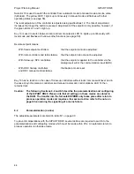
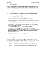
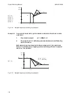
The dead zone element provides the controller with a progressive response; the gain is small or
even zero in the case of small negative deviations, the defined Kp is reached with large negative
deviations.
The factory setting of A is 0. A setting must be made for three-position step controllers
(see page 89).
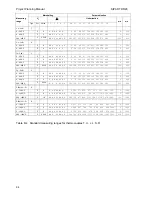
8. Abbreviations
The abbreviations used in this manual, unless already explained in the corresponding text or
tables, have the following meaning:
AE
A
/A
A1/2
BA
BE
BL
BLPS
Analog input
Response threshold
No automatic mode
Alarm monitor 1/2
Digital output
Digital input
Control signal "Blocking of manipulated
variable"
Control signal “Blocking of parameterization
and configuring facility”
TF
Tg
Tn
Tu
Tv
Tw
Ty
T+/T-
v
FiIter time constant for xd
Recovery time
Reset time
Delay time
Derivative action time
Setpoint ramp
Positioning time of motor-driven actuators
Period with two-position controller
Ratio factor
c1
c2
CB
ESR
H
Parameter “Constant 1 (zero)”
Parameter “Constant 2 (factor)”
Control signal “Computer readiness”
Electronic position transmitter
Front command “Manual mode”
wa
we
wE
wES
wi
wS
w
Start-of-scale value ( Setpoint limitation or
Full-scale value
( ratio factor setting range
Remote setpoint
Remote setpoint via serial interface
Local setpoint
Safety setpoint
Effective setpoint
Int
Iy
Front command “Local setpoint”
Current output, manipulated variable
x
xd
Effective actual value (controlled variable)
Negative deviation (w - x)
Kp
Ks
LA
LE
L1 … L7
N
Proportional gain
Transmission gain of system
Full-scale value
(limitation or dead zone
(with two-position controller
Parameter “Start-of-scale value”
Parameter “Full-scale value”
Parameter “Turning points of linearizer”
Control signal “Tracking of manipulated
variable”
ya
ye
yA
yBL
yE
yES
Start-of-scale value (Manipulated variable
Manipulated variable in automatic mode
Blocked manipulated variable
Effective external manipulated variable
Tracking manipulated variable via serial interface
/RB
/RC
Signal “No computer readiness”
Signal "No computer mode”
yH
yN
yR
Manual manipulated variable
Tracking manipulated variable via analog input
Feedback manipulated variable
SES
Si
ta
te
Serial interface
Control signal "Safety mode"
Min. positioning pulse length (switch-on)
Min. positioning pulse pause (switch-off)
yS
Safety manipulated variable
100


