SIPART DR20
Project Planning Manual
X1
INT
+
INT
gn
SP - w
w
i
w
w
X2
w
i
w
a
w
e
T
w
X
0
0
0 0
S20, S21
Display
Key
8
8
8
4
+
-
SES
W
X
Xd
0
2
1
S23
A2
A1
a1
a2
D-element (S27)
see Fig. 3/19
S17
x - tracking
Key
Key
13
8
8
8
0
1
0
1
S19
8
8
8
8
A
A
X1 + c1 + c2
∗
X2
c1
c2
A = H or N or Bl or Si
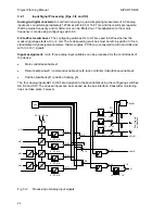
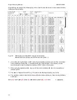
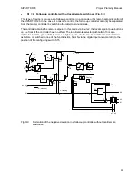
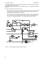
Fig. 3/5
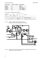
Processing of command variable, calculation of controlled variable and
formation of negative deviation with fixed setpoint controller and disturbance
variable feed-forward at the input
•
S1 = 2 Fixed setpoint controller with disturbance variable feed-forward at the output
Fig. 3/3 also applies to processing of the command variable and formation of the deviation. The
evaluation and the addition of the disturbance variable to the output signal are described in Section
3.2.3 (page 44).
•
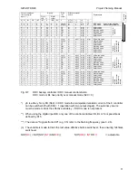
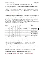
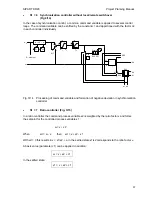
S1 = 3 DDC backup fixed setpoint controller (Fig. 3/6)
In the case of direct digital control (DDC) all control functions are transferred directly from a
process computer (control system), but individual loops, or all loops, are frequently protected by
parallel hardware controllers. Their function is to take over control of the respective loop in a
hitchless manner if the computer fails. During DDC mode (non-faulty), the backup controllers are at
standby, i.e. their outputs are made to track the respective computer manipulated variable. The
negative deviation can also be set to zero in the individual controllers by x-tracking so that control
is continued in a hitchless manner as well as driftfree following switchover.
29


