SIPART DR20
Project Planning Manual
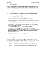
Factory setting of configuring switches:
the factory setting of the configuring switches is always
"0", i.e. also with the S controller where it is essential to reset certain switches (e.g. S2).
It is
therefore always recommendable to check the compatibility of the settings with the desired
operating mode.
6.7
Standard Measuring Ranges for Temperature Measurements Using
Thermocouples
Marshalling:
These settings are carried out using jumpers on the thermocouple
module
6DR2800-8T.
Parameterization:
These settings are carried out using parameters in the basic device.
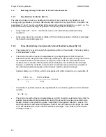
The start-of-scale value (LA) and the full-scale value (LE) must be exactly set during
commissioning using the adjustable resistors accessible at the rear of the thermocouple module.
Caution:
The conditions of use and the continuous operating limits of thermocouples
to DIN 43710 and DIN / IEC 584 must always be observed.
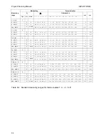
Settings for standard measuring ranges for thermocouples have been prepared in the following
Tables 6/3 and 6/4 :
Marshalling Parametrization
U
0
∆
U
Linearization
Measuring
range
Type
Pol.
Value
1 2 3 4 5
LA L1 L2 L3 L4 L5 L6 L7 LE
wa
we
NiCr-Ni
K
0 - 600
°
C
P
0
AB BC AB BC A
0 76 153 230 306 380 454 527 600
0 600
0 - 900
°
C
P
0
AB AB BC BC AB
0 114 230 343 454 563 673 785 900
0 900
0 - 1000
°
C
P
0
AB BC BC BC BC
0 126 254 378 500 621 744 879 1000
0 1000
0 - 1200
°
C
P
0
BC BC BC AB A
0 149 300 445 589 733 882 1038 1200
0 1200
0 - 1300
°
C
P
0
BC BC BC BC AB
0 160 321 477 631 787 950 1120 1300
0 1300
300 - 600
°
C
P
4/8
AB AB BC A AB
300 338 376 414 451 489 526 563 600
300 600
600 - 900
°
C
P
1/8/16
AB AB BC A AB
600 637 673 710 748 785 823 861 900
600 900
600 - 1000
°
C
P
1/8/16
AB BC A AB AB
600 648 697 746 795 846 896 948 1000
600 1000
750 - 1000
°
C
P
1/2/4/8/16
AB AB A BC AB
750 780 811 842 874 904 936 970 1000
750 1000
Table 6/3 Standard measuring ranges for thermocouple K (NiCr-Ni)
93


