SIPART DR20
Project Planning Manual
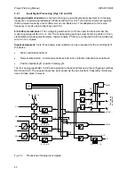
The alarms A1 and A2 are indicated on the four-digit display (4) in the same engineering units as
the setpoint and actual value. The hysteresis is 1 % of the measuring range.
Caution:
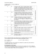
In addition to monitoring on the instrument, alarm signals can also be output
externally using an additional module (page 80). It should be noted that only one
external alarm signal is output at a time.
For example, if the alarm monitors have been programmed for max./max. signalling
(preliminary alarm and main alarm), the preliminary alarm signal is cancelled when the
main alarm signal appears. This only applies to external alarms via an optional module
and not to LED signals on the front panel of the controller.
Digital display of setpoint and actual value or setpoint ratio and actual ratio and limits:
The setpoint, actual value and limits are indicated in engineering units where the start-of-scale
value is scaled by parameter LA and the full-scale value by LE. The factory setting is LA = 0.0 and
LE = 100.0 corresponding to a percentage scale. Configuring switch S20 can be used to adjust the
position of the decimal point, S21 the repetition rate of the displays.
With software version A06 / A07 it is also possible to set the full-scale value LE below the start-of-
scaIe value LA, i.e. to operate the controller with falling characteristic of the actual value.
The setpoint ratio, actual ratio and limit setting are displayed with ratio controllers and ratio
stations. The decimal point is fixed at x
.
xxx so that ratio factors are possible between 0.000 and
9.999 (cf. S1 = 7 and 8).
Functions which depend on the configured type of controller:
•
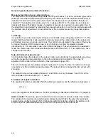
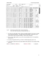
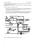
S1 = 0 Fixed setpoint controller (Fig. 3/4)
In this type the controller only processes the main controlled variable x1 as an analog input signal.
The setpoint can be adjusted using the setpoint pushbuttons (12) if the two green LEDs (9.1 and
14) light up on the front of the device, i.e. with local mode and setpoint display. It is thus possible to
block the intentional or unintentional adjustment of the setpoint by pressing pushbutton (13) (LED
14 then does not light up). The x-tracking function (with manual or tracking mode or with blocking
of the manipulated variable or safety manipulated variable) is independent thereof, i.e. x-tracking
(with S17 = 1) is effective with and without LED 14).
In line with the definition of the fixed setpoint controller, the device does not accept an external
setpoint with this programming.
27


