SIPART DR20
Project Planning Manual
3.2.3 Control
Algorithm
This section describes the following functions:
−
Filtering of negative deviation xd
−
Display of negative deviation
−
Response threshold of negative deviation
−
Matching to direction of action
−
D element
−
P/PI control algorithm
−
Hitchless switchover to automatic mode
−
Limitation of controller output signal yA
Filtering of negative deviation:
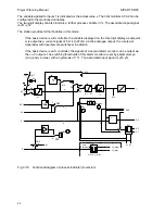
A 1st order filter with the time constant tF acts on the negative
deviation xd. The filter is switched on when the display of parameter tF jumps from OFF to 1 s and
can be adjusted within wide limits. The time tF should only be set so large that the control loop
does not oscillate (tF < recovery time Tg).
Display of negative deviation:
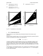
From software version A08 onwards the display 1 can be
configured to indicate either the negative deviation xd (w-x) or the deviation xw (x-w). Therefore the
following details are valid for the negative deviation or the deviation, depending on the selection of
configuring switch S25 (see page 20). The filtered negative deviation is indicated on display 1. This
display has a total of 21 vertical LEDs; the factory setting enables a deviation of max.
±
10 % to be
displayed referred to the measuring range. The display range can be modified using configuring
switch S25 between
±
2.5 % and
±
40 % negative deviation. The 21 LEDs are divided as follows:
10 red LEDs
to display a positive deviation, i.e. the setpoint is larger than the actual
value. In the factory setting, the 1st LED lights up with xd
≥
0.5 %, the
2nd LED above xd
≥
1.5 % up to the 10th LED above 9.5 %. The result is a
red column which becomes longer as the negative deviation increases and
thus as the danger increases.
1 green LED
lights up in the center of the 21-part LED string if
|
xd
|
is < 1 % in the
factory
setting.
10 red LEDs
to display a negative deviation, i.e. the actual value is larger than the
setpoint. The display function corresponds to that of the positive deviation
display but in the negative range.
This function (based on the factory setting) means that the following range has a very fine
resolution:
xd +
1.0 to
<
+ 1.5 %
only 1st red LED (pos.) lights up
xd +
0.5 to
<
+ 1.0 %
green LED and 1st red LED (pos.) light up
xd > -
0.5
to
<
+ 0.5 %
only the green LED lights up
xd > - 1.0
to
- 0.5 %
green LED and 1st red LED (neg.) light up
xd > - 1.5
to
- 1.0 %
only 1st red LED (neg.) lights up
The replaceable scale label (2) is printed on the front with the standard range
±
10 % for xd. The
free area can be labelled individually with additional information:
e.g.
−
Measurement point
−
Measuring range
−
Dimension of measured variable
−
Alarm monitoring
43


