SIPART DR20
Project Planning Manual
6DR2801-8B
3 / 4
3 / 3
3 / 2
3 / 1
M
TTL
24 V
TTL
24 V
TTL
24 V
TTL
24 V
TTL
24 V
3 / 5
+
∆
y
-
∆
y
A2
A1
BLPS
4x
≥
17.5 V
≤
30 mA
L +
Terminal
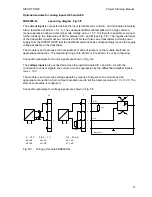
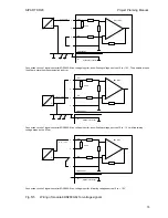
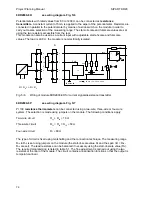
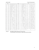
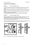
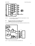
Fig. 5/10
Connection diagram of module 6DR2801-8B for digital outputs A1 / A2 and
±
∆
y as well as digital input BLPS
5.2.2
Wiring the Serial Interface and the SIPART Bus Driver
6DR2803-8A (V.28 point-to-point serial interface)
Insert in slot 4. Use configuring switches S42 to S48 to establish communications procedure.
V.28 (
≤
50 m )
6K81
+ 10 V
+ 1
- 10 V
- 1
6DR2803-8A
+ 1
x1
x2
x3
point-to-point
Bus
M
4 / 2
4 / 7
4 / 8
4 / 3
+ 24 V
+ 10 V
+ 10 V
- 10 V
+ 24 V
M
- 5 V
5 V
± 10 V
TxD
RxD
Remote system
Common
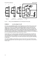
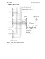
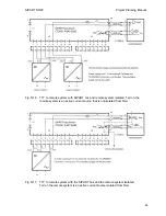
Fig. 5/11
Wiring of V.28 point-to-point SES module 6DR2803-8A
81

