SIPART DR20
Project Planning Manual
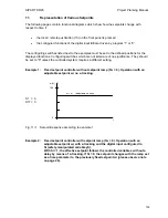
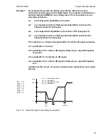
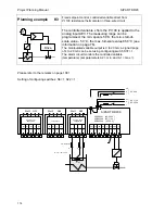
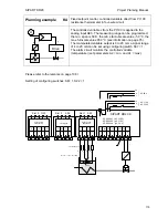
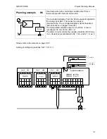
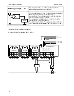
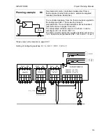
Example 4:
Two-setpoint mode according to configuration described on page 33.
Both setpoints can be called into the four-digit display using pushbutton 8
and adjusted using pushbutton 12 on the front of the controller. The switch
over between w1 (safety setpoint wS) and w2 (local setpoint wi) is carried out
by the local/remote switch 13. A setpoint ramp Tw > 0 is switched on.
S1 = 5
S15
≠
3
S17 = 0
S18 = 1
S19 = 1
S24 = 1
S42 = 2
100
0
w
1
w
2
INT
INT
t
w (%)
w
1
= w
S
(adjustable on front)
w
2
= w
i
(adjustable on front)
Fig 1/4
Setpoint response according to example 4
S19 = 0
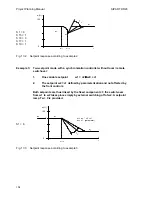
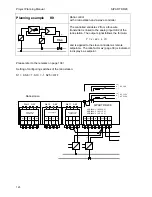
Example 5:
Two-setpoint mode as already described in example 4, but in this case the
local setpoint wi is made to track the effective setpoint w. The following
function is then achieved: if a switch is made to local using pushbutton 13
whilst the setpoint increases, the last value is retained as wi until switched
back to remote again. If necessary, wi can be changed on the front panel in
local mode. Once wS has been reached, another setpoint can be reached
using x-tracking if pushbutton 10 is switched to manual mode. The setpoint
moves towards wS again as soon as a switch is made to automatic mode
again.
S1 = 5
S15 = 3
S17 = 1
S18 = 1
S24 = 1
S29 = 1
100
0
w
1
w
2
x = w
INT
INT
H
t
w (%)
CB
CB
INT
w
2
A
Fig. 11/5
Setpoint response according to example 5
105


