Project Planning Manual
SIPART DR20
3.2.5 Restart
Conditions
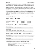
Configuring switch S41 is used to define the restart conditions after a power failure or if the
processor had detected a fault. If it is set to position 0, 1, 2 or 3, display 4 is flashing after a restart
of the controller. This signal can be acknowledged by pressing pushbutton 8. From software
version A09 onwards configuring switch S41 has the additional positions 4, 5, 6 and 7 with the
same restart conditions but without flashing of display 4 (see page 21).
The SIPART DR20 does not start with the last operating states since these cannot be transferred
fast enough to the non-volatile memory in the case of a power failure. However, the local setpoint
wi is loaded into the EEPROM if it has not been changed for approx. 5 minutes and is available as
the "last w". This means that the last setpoint entered manually or via the serial interface is present
providing it was constant long enough. The last manipulated variable is not retained.
The possibilities for S41 listed in the configuring table are self-explanatory.
3.2.6
Optical Signalling of Functions and Operating States
Various functions and operating states can be activated either by manual interventions on the
control keyboard or via a digital function depending on the various configuring switch settings, as
described in the previous sections. Optical signalling of these functions and operating states is on
the two LEDs 11 and 14 either as steady lights or flashing lights with different cycles.
All functions which refer to setpoint control are displayed on the green LED 14, all states
concerning the manipulated variable are signalled on the yellow LED 11. The associated variables
can be adjusted with the flashing cycle 0.9 and with steady light 1.
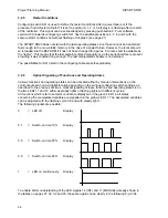
The following signals are possible:
0
= LED off
Display :
0.1
= Switch-on time 10%
Display :
0.5
= Switch-on time 50 %
Display :
0.9
= Switch-on time 90 %
Display :
1
= LED on continuously
Display :
To enable better understanding of the LED signals 14 (INT) and 11 (MANUAL) already shown in
the tables on pages 31, 32, 34 and 35, these are again shown clearly in the following Fig. 3/34.
58

