SIPART DR20
Project Planning Manual
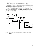
General, recurring functions :
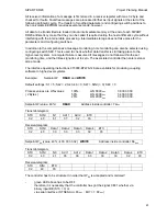
Possible operating modes:
(The optical signals are shown in Section 3.2.6)
•
A =
Automatic operation with y = yA. This mode can be interrupted by digital signals
(see also page 23) as well as by manual interventions.
•
BL =
Blocking of output. The last manipulated variable signal ly or the duty factor is
retained with K controllers and S two-position controllers, no manipulated variable
signal is output anymore with three-position step controllers.
•
Si =
Safety manipulated variable: y = yS is preset as the output signal. yS can be set as a
parameter. The manipulated variable therefore assumes the parameterized safety
value according to its set speed except with a three-position step output with internal
position feedback. The output -
∆
y has a continuous contact if yS is configured < 50 %
with this output configuration,
∆
y has a continuous contact if yS is
parameterized larger than 50 %.
•
N =
Tracking or DDC backup mode: y = yN or y = yES. This operating mode can only be
implemented with K controllers or with S controllers with a two-position output. Three-
position step controllers with external position feedback, the tracking signal can be
tracked via the serial interface (yES). No tracking of the manipulated variable is
possible in three-position step controllers with internal position feedback.
•
H =
Manual operation: y = yH. The manipulated variable is adjusted using the two keys
5.1 and 5.2.
Only one control signal can be defined via the digital input BE according to the position of switch
S15. The priority is Si before BL before N when entering the control signals via the serial interface
SES. Si always has priority over H
,
but the priority between H
,
N and BL can be changed
depending on the position of S29.
If transmitter monitoring is set using configuring switch S11, the monitored signal can be used to
switch to manual mode depending on S30, when the range limits are violated.
The switchover facility between manual and automatic operation can be suppressed by configuring
switch S31:
S31 = 1
Automatic operation only
S31 = 2
Manual operation only
Activation of the manual/automatic pushbutton in this mode causes blocking
of the manipulated variable adjustment and the yellow LED 11 is
extinguished. This function is of interest, e.g. when using the controller as a
manual control station.
47

