Project Planning Manual
SIPART DR20
3.2.1
Input Signal Processing (Figs. 3/2 and 3/3)
Analog-to-digital conversion
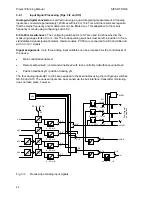
is carried out using a quasi-integrating measurement. All analog
inputs are converted approximately 120 times within 20 or 16.67 ms and the results averaged so
that the mains frequency and its harmonics can be filtered out. This adaptation to the mains
frequency is made using configuring switch S3.
0/4 to 20 mA switchover:
The configuring switches S4 to S7 are used to define whether the
measuring range starts at 0 or 4 mA. The corresponding switches must be left in position 0 if non-
standardized signals (potentiometers, thermocouples, Pt100) are connected to AE3 and AE4 and
with 0 to 10 V signals.
Signal assignment:
Up to three analog input variables can be processed for the control tasks of
the device:
•
Main controlled variable x1
•
Remote setpoint wE / command variable x2 with ratio controller / disturbance variable x2
•
Position feedback yR / position tracking yN
The four analog inputs AE1 to AE4 are assigned to these variables using the configuring switches
S8, S9 and S10. The unused inputs can be scanned via the bus interface, transmitter monitoring
does not take place, however.
S4
1
0
SES
0/2/4/6
1/3/5/7
S11
-2
U
U
A
D
AE4
A
D
AE3
A
D
AE2
A
D
AE1
S3
50 Hz
60 Hz
4 .. 20 mA
4 .. 20 mA
4 .. 20 mA
4 .. 20 mA
S5
1
0
S6
1
0
S7
1
0
S9
0
1
S10
0
1
-1
S8
0
1
S12
0
1
S13
0
1
x2/wE
x1
yR/yN
1
S14
0
LA, L1, .. L7, LE
-3 .. 103%
-3 .. 103%
-3 .. 103%
2/3/6/7
0/1/4/5
MuSt
1
2
Y
Fau
lt sign
al
on dis
p
lay
4
4/5/6/7
0/1/2/3
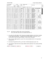
Fig. 3/2
Processing of analog input signals
22

