SIPART DR20
Project Planning Manual
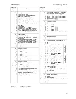
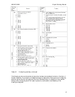
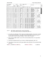
Structuring
switches
and
positions
Function
S39
-9
-8
-7
:
:
-1
0
1
:
:
8
9
10
Minimum control pulse length te
(only with S2 = 2 or 3)
20 ms
40 ms
60 ms
:
:
180 ms
200 ms
220 ms
:
:
360 ms
380 ms
400 ms
S-c
ontrol
le
r
S40
-9
-8
-7
:
:
-1
0
1
:
:
8
9
10
Min. control pulse pause ta (function as S39)
20 ms
40 ms
60 ms
:
:
180 ms
200 ms
220 ms
:
:
360 ms
380 ms
400 ms
S41
0
1
2
3
Restart conditions after power failure:
Automatic operation, remote, with the last w
or wv, y begin, with y
S
with S controllers
(S2 = 2 and 3) with the last position
Automatic operation, local,
with w = w
s
or wv = wv
S
, y as S41 = 0
Manual operation, remote, with the last or wv
and y = y
S
with S controllers (S2 = 2 and 3)
with the last position
Manual operation, local
with w = w
S
or wv = wv
S
, y as S41 = 2
With flashing of display 4
Startup condition
s
4
5
6
7
Automatic operation, remote, with the last w or
wv, y begins with y
s
, wIth S controllers (S2 = 2
and 3) with the last position
Automatic operation, local,
with w = w
s
or wv = wv
s
, y as S41 = 0
Manual operation, remote, with the last w or wv
and y = y
s
, with S controllers (S2 = 2 and 3)
with the last position
Manual operation, local
with w = w
s
or wv = wv
s
, y as S41 = 2
Without flashing of
display 4
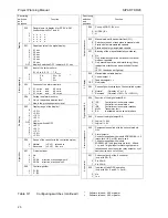
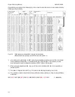
Structuring
switches
and
positions
Function
S42
0
1
2
Serial interface, only in conjunction with optional
module 6DR2803-8A:
Without; controller transmits all variables, receives
none
With; controller transmits all variables, receives
only parameters and structuring switches
With; controller transmits all variables, receives
parameters, structuring switches and W
es
, Y
es
,
STes (CB, BL, Si and BA)
S43
0
1
2
3
4
5
Data transmission rate:
9600 bit/s
4800 bit/s
2400 bit/s
1200 bit/s
600 bit/s
300 bit/s
S44
0
1
Vertical parity:
Even
Odd
S45
0
1
2
Longitudinal parity position:
Without
After ETX
Before ETX
S46
0
1
Longitudinal parity:
Normal
Inverted
S47
0
1
2
:
:
31
Station number (address):
0
1
2
:
:
31
Serial interface
S48
0
1
2
3
:
:
24
25
Time monitoring CB
ES
:
Without
1 s
2 s
3 s
:
:
24 s
25 s
Table 3/1
Configuring switches (continued)
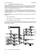
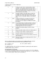
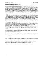
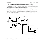
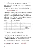
The following sections demonstrate and describe hardware and software functions in the form of
function diagrams. The sequence of diagrams largely corresponds to the sequence of configuring
switches except that the input signal processing is handled before the diagrams of the possible
settings of the configuring switch S1 (device types) to enable better understanding of the
subsequent diagrams.
21


