SIPART DR20
Project Planning Manual
•
S2 = 2
S three-position step output for motor-driven actuators with internal position
feedback (Figs. 3/30, 3/31)
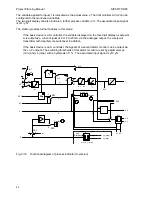
With this type of controller, an internally simulated position control loop is connected to the PID
control algorithm. The integral response of the final control element is simulated by an integrator
with an adjustable positioning time (parameter Ty) which replaces the position feedback. To
prevent the internal integrator and the PID output from becoming saturated as time progresses,
both variables are reset by the same amount if necessary. To prevent integral saturation, the rise
rate of the I component is limited to Ty by the series-connected K controller.
The variable y is only a relative manipulated variable with this output configuration. Therefore
limitation of the manipulated variable using parameters ya and ye, a parametrizable safety setting
yS and a pure P control are not possible.
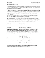
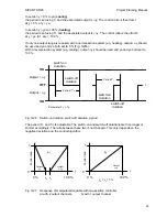
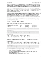
The position controller has a minimum pulse length te adjustable using configuring switch S39 and
a minimum pulse pause ta adjustable using S40. The minimum pulse length te results in a
response threshold as follows:
Switch-on :
Aee =
2
∗
te / Ty
Switch-off :
Aea =
te / Ty
Hysteresis:
Aee - Aea =
te / Ty
See section 7.2.2 for the setting criteria of ta and te
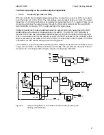
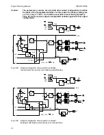
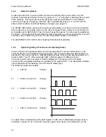
The switchover facilities of the three-position step controller with internal position feedback are
shown in Figs. 3/30 and 3/31.
S34
0
2
1
3
4
RB
RC
SES
MuSt
H
0
1
BA
S35
y'
y
A
y
R
/y
N
y
H
y
S
H
+
+
-
H
S31
0
2
1
y
Bl + DDC
Si
+
-
S32
0
1
t
A
t
E
-
∆
y
y
+
∆
y
S33
S21
0 0
DDC = RC = INT
∗
CB
y
S
> 50%
y
S
< 50%
T
Y
1
0
with S
1
=
9
Fig. 3/30
Output configuration of three-position step controller with internal position feedback,
manual mode has priority over blocking
55


