Project Planning Manual
SIPART DR20
•
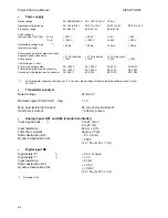
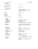
Power supply
Rated voltage
Operating voltage range
Frequency range
Peak voltages:
Non-periodic (VDE 160)
1.3 ms
10
µ
S
Permissible voltage dips
**)
(at maximum load)
Power consumption (at maximum load):
Apparent power (inductive)
Active power
Test voltages: (1 min)
Primary / secondary side
Primary side/protect. earth conductor
Secondary side/protect. earth conductor
AC 220/230/240 V
AC 195 to 276 V
48 to 63 Hz
≤
780 V
≤
1500 V
≤
30 ms
≤
21 VA inductive
≤
13W
AC 1500 V
AC 1500 V
AC 500 V
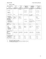
AC 110/115/120 V
AC 97 to 138 V
48 to 63 Hz
≤
390 V
≤
1500 V
≤
30 ms
≤
21 VA inductive
≤
13W
AC 1500 V
AC 1500 V
AC 500 V
UC 24 V
AC 20 to 28 V
48 to 63 Hz
≤
78 V
≤
500 V
≤
30 ms
≤
21 VA inductive
≤
13W
AC 500 V
DC 700 V
DC 700 V
DC 20 to 35 V
≤
78 V
≤
500 V
≤
30 ms
≤
13W
AC 500 V
DC 700 V
DC 700 V
**)
The transmitter supply can fall by up to 5 V, the max. load voltage of the manipulated variable current Iy from
18 to 13 V.
•
Transmitter supply L+
Rated voltage
Residual ripple (100/120 Hz) Upp
Max. permissible load current
Short-circuit current
20 to 26 V
≤
1 V
60 mA, short-circuit-proof
< 200 mA, puIsed
•
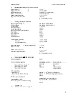
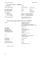
Analog inputs AE1 and AE2 (standard controller)
Input signal range
*)
Input resistance
Filter time constant
Static destruction limit
Dynamic destruction limit
0 to 20 mA or
4 to 20 mA
249
Ω
±
0.1%
approx. 25 ms
- 8 / + 30 mA
±
500 V
(1.2 / 50
µ
S, Ri = 13
Ω
)
•
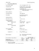
Digital input BE
Signal state "0"
*)
Signal state" 1"
*)
Input resistance
Static destruction limit
Dynamic destruction limit
≤
4.5 V or open
≥
13 V
≥
27 k
Ω
±
+ 35 V
±
+ 500 V
(1.2 / 50
µ
S, Ri = 13
Ω
)
*)
Referred to M
64


