Project Planning Manual
SIPART DR20
S34
0
2
1
3
4
RB
RC
SES
MuSt
H
0
1
BA
S35
y'
y
A
y
R
/y
N
y
H
y
S
H
+
+
-
H
S31
0
2
1
y
N + DDC
Si
S32
0
1
S33
S21
0 0
DDC = RC = INT
∗
CB
1
0
with
S
1
= 9
y
ES
SES
S42
0/1
2
Bl
SES
Iy
1
0
S37
D
A
U
I
DDC
S38
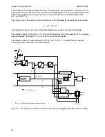
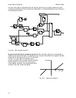
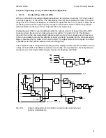
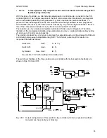
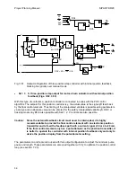
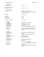
Fig. 3/25
Output configuration of K controller,
tracking mode/blocking has priority over manual mode
•
S2 = 1
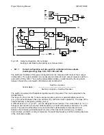
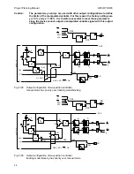
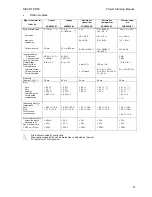
Output configuration as S two-position controller with two outputs
(heating/cooling) (Figs. 3/26, 3/27,3/28 and 3/29)
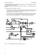
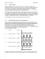
The switchover facilities of this output configuration can be compared with those of the K output
configuration. The output variable can only assume two states for each output, however: switch-on
and switch-off (Fig. 3/26). The resulting manipulated variable y is determined by the duty factor
between the switch-on and switch-off durations and is defined as
Switch-on
duration
Control Ratio =
----------------------------------------------------------------
Switch-on du Switch-off duration
The switch-on and switch-off durations together result in the period. This can be adjusted in the
SIPART DR20.
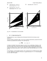
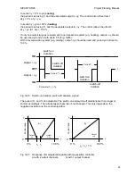
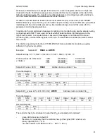
The range of y from 0 to 100 % can be divided into two sections. A parametrizable dead-zone
(ye - ya) is present between these two sections (Fig. 3/27a and note on page 53). The slope of the
output sensitivity is changed by shifting ya or ye.
A different period (T + (Ty) and T -) can be assigned to each section. The control ratio 0 to 1 is run
through in each section, where the shortest switch-on or switch-off duration is limited to 1 % of the
period. The period must therefore be set such that the most favorable compromise is found
between the minimum permissible switch-on time of the final control element (e.g. contactor,
solenoid valve, ventilator, cooling compressor), the switching frequency and the resulting response
of the controlled variable.
52

