SIPART DR20
Project Planning Manual
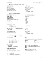
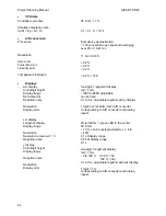
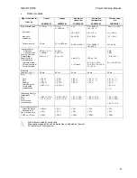
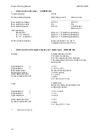
Optional modules for analog inputs AE3 and AE4:
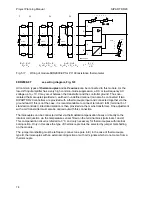
6DR2800-8J
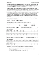
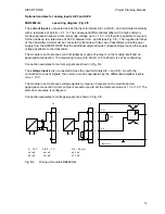
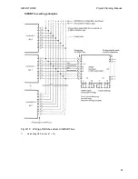
see wiring diagram, Fig. 5/3
The
current input
is connected across the input terminals AE + and AE - and terminated internally
with a resistance of 49.9
Ω
±
0.1 %. The subsequent differential amplifier with a high common-
mode suppression allows a common-mode voltage up to + 10 V. It is therefore possible to connect
further loads up to a total value of 500
Ω
between AE - and M (see Fig. 5/3). The negative terminal
of the transmitter circuit must be connected to M. Note with two-wire transmitters and with power
supply from the SIPART DR20 that the additional external loads correspondingly reduce the supply
voltage available to the transmitter.
The module is set to process current signals by means of jumpers on the module itself and an
appropriate connection. The measuring range (0 to 20 mA or 4 to 20 mA) is set by configuring.
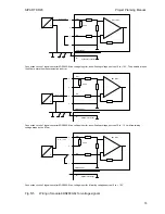
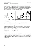
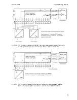
Connection examples for current signals are shown in Fig. 5/4.
The
voltage input
is also connected across the input terminals AE + and AE -. As with the
connection to current signals, the common-mode suppression by the differential amplifier input is
max. + 10 V.
The module is set to process voltage signals by means of jumpers on the module and an
appropriate connection circuit. Jumpers are also used to set the full-scale value of 1 V or 10 V, The
start-of-scale value is configured.
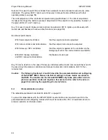
Connection examples for voltage signals are shown in Fig. 5/5.
Ι
3
1
2
4
6DR2800-8J
+
-
AE +
U
0 ... 10 V
U
49.9
2
4
U
H
+
-
AE -
0/0.2 ... 1 V
0/4 ... 20 mA
Ι
U
H
+
-
0 ... 500
Ω
x4
x6
x5
x8
x7
x9
x5 = x6
x8 = x9
x4 = x5
x7 = x8
x4 = x5
x7 = x8
Fig. 5/3
Wiring of module 6DR2800-8J
73


