Project Planning Manual
SIPART DR20
Selector 10 is used to switch the controller from automatic mode to manual mode and vice versa
(hitchless). The yellow LED 11 lights up continuously in manual mode and flashes with other
operating states (see page 58).
The local setpoint wi of the controller is adjusted using pushbuttons 12. The rate of adjustment
increases the longer the button is pressed. Adjustment of the setpoint is only possible, however, if
the green LEDs 9.1 and 14 light up.
Key 13 is used to switch between local and remote setpoint. LED 14 lights up continuously with
local mode and flashes with various other functions (see page 58).
Remote setpoint means:
that backup mode is set
-
With fixed setpoint controllers
that the setpoint cannot be adjusted
that the setpoint ratio cannot be adjusted
that the setpoint is applied to the controller via the
analog input wE or the communication input (SES)
-
With ratio controllers and ratio stations
-
With follow-up / SPC controllers
-
With DDC backup controllers
and DDC manual control stations
Key 13 has no function in the case of follow-up controllers without local / remote switchover and in
the case of synchronization controllers and manual / automatic control stations. LED 14 then
remains dark.
Caution: The following Sections 6.2 and 6.3 describe the parameterization and configuring
of the SIPART DR20. Please note that all settings in these modes are stored in
the RAM. The transfer into the fail-safe EEPROM only takes place after return to
process operation mode and requires a few seconds. Also refer to the note on
page 89 concerning the signalling of a mains failure.
6.2 Parameterization
(on-line)
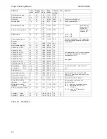
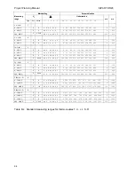
The adjustable parameters are listed in table 6/1 on page 90.
To prevent maloperations with the SIPART DR20, several actions are required to switch to the
parameterization and configuring modes which must be made within 20 s. An automatic return to
process operation is otherwise made.
88


