Project Planning Manual
SIPART DR20
6DR2800-8R
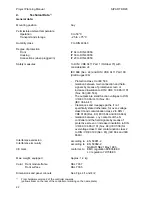
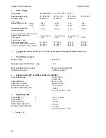
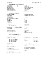
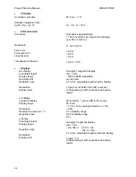
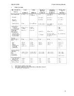
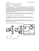
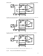
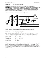
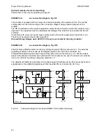
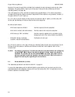
see wiring diagram, Fig. 5/6
Potentiometers with rated values from 80 to 1200
Ω
can be connected as
resistance
transmitters
. A constant current of 5 mA is applied to the wiper of the potentiometer. Resistors are
connected in parallel to the potentiometer by means of a slide switch on the module in order to
carry out coarse selection of the measuring range. The start-of-scale and full-scale values are set
using the two resistors accessible from the rear.
This module can also be used as a current input with adjustable start-of-scale and full-scale
values. The load is 49.9
Ω
, the module is not electrically isolated.
R
3
1
2
4
6DR2800-8R
+
-
0
49.9
Ι
K
200
Ω
5 mA
R
Ι
R = R
A
+
∆
R + R
E
Ι
243
332
U
REF
max.
20 mA, 1 k
Ω
,
500
Ω
,
200
Ω
2
4
R
A
∆
R
R
E
U
H
+
-
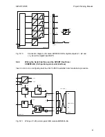
Fig. 5/6
Wiring of module 6DR2800-8R for current signals/resistance transmitter
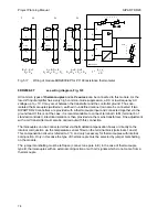
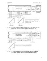
Pt 100
resistance thermometers
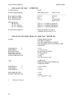
can be connected using a two-wire, three-wire or four-wire
system. The selection is made using jumpers on the module. The following conditions apply:
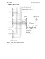
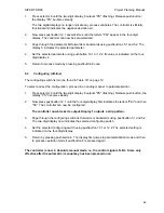
6DR2800-8P
see wiring diagram, Fig. 5/7
Two-wire circuit
R
L1
+ R
L4
≤
10
Ω
Three-wire circuit
R
L1
= R
L3
= R
L4
≤
50
Ω
Four-wire circuit
R
L
≤
80
Ω
The type of circuit is fixed using marshalling and the connection technique. The measuring range
R
tA
to R
tE
is set using jumpers on the module (the start-of-scale value R
0
and the span
∆
R = R
tE
-
R
tA
are set). The lead resistance can be balanced if necessary using the start-of-scale value (R
0
).
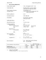
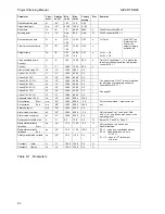
The required programming is listed in table 5.1. The fine adjustment is carried out using the two
resistors at the rear of the module. The circuit contains a linearization function so that the output is
temperature-linear.
76

