Project Planning Manual
SIPART DR20
X1
w
S
INT
+
INT
gn
SP - w
w
i
w
w
X2
1
0
S18
w
i
CB
CB
INT
INT
w
a
w
e
T
w
0
1
X
0
0
0 0
S20, S21
Display
Key
8
8
8
4
+
-
SES
W
X
Xd
0
2
1
S23
A2
A1
a1
a2
D-element
S17
H
H
1
0
S17
x - tracking
Key
Key
13
8
8
8
H
S29
Si v Bl
Si v Bl
Si v Bl
H
H
0
1
0
1
S19
8
8
8
8
S19=1
is not used
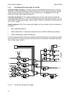
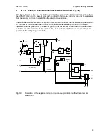
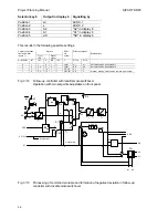
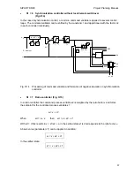
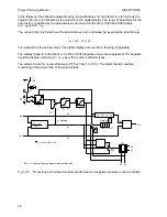
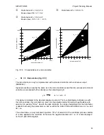
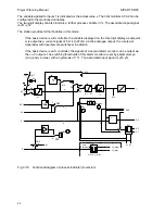
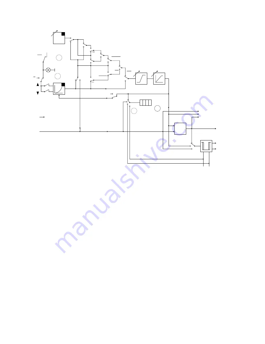
Fig. 3/6
Processing of command variable and formation of negative deviation with DDC backup
fixed setpoint controller
DDC mode corresponds to tracking mode of other types of controller except that the switchover to
tracking mode is not made via the control signal N but as a function of the CB signal (also possible
via the serial interface) and the local/remote selector pushbutton:
DDC mode = RC = CB
∗
/I
(with S29 = 0, see Fig. 3/7)
DDC mode = RC = CB
∗
/I
∗
/H
(with S29 = 1, see Fig. 3/8)
No status LED lights up on the controller in DDC mode. The value which becomes effective upon
computer failure is always indicated as the setpoint. If the computer fails (CB = 1
Æ
0), the green
LED of the "Local" display (14) flashes and the controller continues to operate with the displayed,
internal setpoint. After switching over to local mode (green LED 14 steady), the setpoint can be
adjusted manually. A clear display of the optical signals is shown in Fig. 3/34 on page 59.
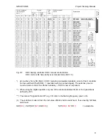
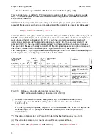
The switchover in the output circuit is explained in the description of section 3.2.4. The following
tables (Figs. 3/7 and 3/8) provide a complete summary of the signals and the effective setpoints
and manipulated variables depending on the front-panel signals, control signals and configuring
switches S17, S18 and S29. The version in Fig. 3/7 is used if manual mode is to be selected
directly following a computer failure.
30


