Project Planning Manual
SIPART DR20
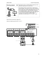
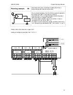
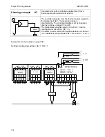
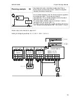
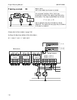
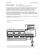
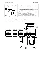
Planning example
K11
Ratio control
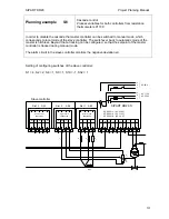
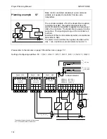
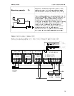
Four-wire transmitters are provided for process
variable and command variable
W
X2
y
Drive
X1
The process variable x1 is connected to analog input
AE1, the command variable x2 is linked to analog
input AE2.
Signal range of both inputs is 0 to 20 mA as well; it
can be reconfigured to 4 to 20 mA (S37 = 1).
The alarm circuit monitors the process ratio factor xv
for max./min. deviations.
For adjustment of the ratio factor range see page 38.
Please refer to the remarks on page 108 !
Setting of configuring switches: S1 = 7, S10 = -1, S22 = 1
AE1
AE2
BE
BA
L+
GND GND
Iy
1
2
3
4
5
6
7
8
SIPART DR20 K
6DR2004-1 (AC 230 V)
6DR2004-2 (AC 115 V)
6DR2004-4
(UC 24 V)
1
2
3
4
1
2
3
4
1
2
3
4
PE
N
L
AC 115 V
AC 230 V
⎫
⎬
⎭
PE
N
UC 24 V
L
⎫
⎬
⎭
Slot 3 GW
Slot 2 AE4
Slot 1 AE3
5
M1
A1
R1
A2
M2
not equipped
Option module
6DR2801-8A
M
M/A
S
E
x1
not equipped
I
I
I
y
+
-
+
-
+
+
-
-
x2
124

