SIPART DR20
Project Planning Manual
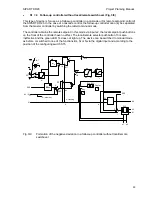
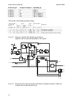
The device is switched to local mode with configuring switch positions 6 to 11, a CB switchover
from 0 to 1 and with front switch 13 in position "Remote". The computer coupling is only achieved
again by manual switching back to remote mode. The controller operates "With CB
acknowledgement".
Option module
6DR2801-8B
INT
INT
CB
ES
S42
0/1
·
S15
0 ... 5
6 ... 11
local
S42
≥
2
0/1
2
+
BE
ES
BE
NE
ES
Si
ES
Bl
ES
SES
BE
&
&
RC
H
RB
MuSt
SES
BA
0
1
S35
CB
S34
≥
&
&
≥
2
≥
≥
&
BLPS
N
Si
Bl
S16
0
1
0/6
1/7
4/10
3/9
5/11
2/8
S15
S42
S42
S42
2
2
0/1
0/1
0/1
0
1
2
3
4
SES
BL
MuSt
INT
A2
A1
H
yE
CB
Si
N
BE
PS
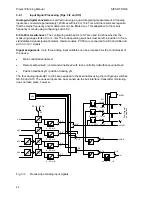
Fig. 3/3
Digital functions via digital input/output and the serial interface (including status signals)
3.2.2
Input Signal Processing and Switchover
The following functions are explained in this section:
•
Manual setpoint input w
i
or setpoint ratio w
v
•
x-tracking
•
Setpoint limiting and setpoint ramp
•
Formation of negative deviation
•
Alarm monitor
•
Digital display of setpoint and actual value or the setpoint and actual ratio factor
and the limits
and, depending on the possible types of devices:
•
Switchover and calculation of the setpoint w or the setpoint ratio factor
•
Calculation of the controlled variable x
25


