Project Planning Manual
SIPART DR20
3.2 Software
The program of the SIPART DR20 operates with a fixed cycle time of 100 ms. A process image is
generated at the start of each routine. The analog and digital inputs and actions on the front keys
are acquired and the process variables transferred which are received from the serial interface. All
calculations are carried out on these input signals according to the stored functions. The data are
then output to the display elements, the D/A converter and the digital outputs and the calculated
variables are stored ready for the transmitter of the transmission interface. The program is
interrupted every 20 ms in the S controllers in order to switch off the S outputs to obtain a good
resolution. Data transfer is also executed in interrupt mode.
The ROM of the SIPART DR20 contains a large number of dedicated functions for the control of
process plants, machines and apparatus. The user can program the controller by selecting the
desired functions using the configuring switches. The total controller function results from the
combination of individual configuring switches. Programming knowledge is not required for the
settings. All settings are made on the front of the SIPART DR20 without an additional programmer.
The problem-specific program produced in this manner is stored in the non-volatile part of the data
memory and is therefore protected against power failure.
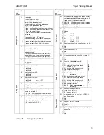
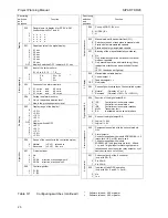
There are 48 configuring switches (S1 to S48). A setting corresponding to the desired function can
be selected for each switch from a function table.
The factory settings of the configuring switches are always "0". This corresponds to the most
common setting of the individual functions so that only a few switches need be set selectively in
most cases during start-up. It is always advisable, however, to compare the compatibility of the
various configuring switch positions with the actual problem.
Configuring switches 1 and 2 are of fundamental importance. S1 is used to define the type of
controller and thus the signal processing and linking at the input as well as the switching response
of the output circuit. S2 is used to define the output configuration. The functions of the following
configuring switches S3 to S40 correspond to the logical sequence of signal processing. Switches
S41 to S48 are used to define general functions such as restart conditions and data transmission
via the serial interface.
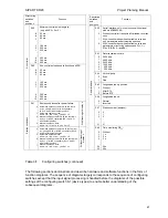
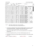
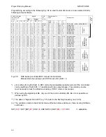
The complete configuring switch table (Table 3/1) follows on the next pages. Detailed information
is then provided on the individual functions and links.
18


