SIPART DR20
Project Planning Manual
Functions depending on the possible output configurations:
•
S2 = 0
K output (Figs. 3/24 and 3/25)
With a K controller the resulting manipulated variable y is output as a current Iy. S37 can be used
to set the range to 0 or 4 to 20 mA. The output stage can only output positive currents. The signal
range from 4 to 20 mA must therefore be selected if a signal less than 0 % is required. Open-circuit
monitoring which links the output signal Iy through the final control element and the input yR/yN
(with transmitter monitoring = S11) is only possible in this signal range.
Configuring switch S38 is used to define whether the output current is to be switched off in DDC
mode as long as the device is in backup mode (only with S1 = 3 and 9, S2 =0). This facility is
required if more than one manipulated variable output (e.g. from the controller and a computer) is
to act on an actuator and only one output may apply a current. Feedback into the controller output
stage is prevented by the diode in the current output. The output stage of the computer, connected
in parallel, must then also be equipped with a blocking diode.
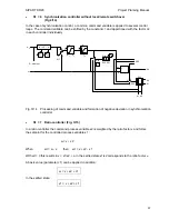
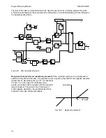
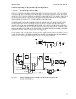
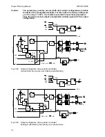
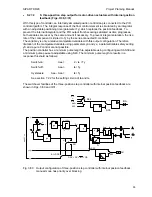
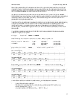
The complete K output configuration including position display and all switchover facilities is shown
in Figs. 3/24 and 3/25. The difference between the two figs. is the preselection of priority between
manual mode or tracking mode/blocking by means of configuring switch S29.
S34
0
2
1
3
4
RB
RC
SES
MuSt
H
0
1
BA
S35
y'
y
A
y
R
/y
N
y
H
y
S
H
+
+
-
H
S31
0
2
1
y
N + DDC
Si
S32
0
1
Iy
S33
S21
0 0
DDC = RC = INT
∗
CB
1
0
with
S
1
= 9
y
ES
SES
S42
0/1
2
Bl
SES
1
0
S37
D
A
U
I
DDC
S38
Fig. 3/24
Output configuration of K controller, manual mode has priority over
tracking mode/blocking
51

