


Connecting
4.3 Control/status interface - X8
SINAMICS V90, SIMOTICS S-1FL6
126
Operating Instructions, 04/2019, A5E36037884-007
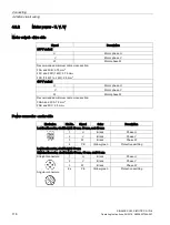
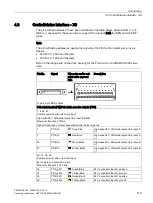
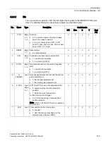
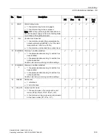
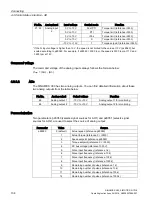
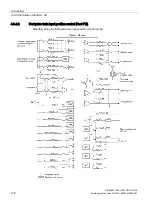
No.
Name
Type
Description
Control mode
PTI
IPos
S
T
Fast
PTI
24
REF
Edge
0→1
Set reference point with digital input or refer-
ence cam input for reference approaching
mode.
•
0→1: reference input
X
✓
X
X
X
25
SREF
Edge
0→1
The reference approach will be started with the
signal SREF.
•
0→1 start reference approach
X
✓
X
X
X
26
STEPF
Edge
0→1
Step forward to the next fixed position setpoint.
•
0→1 start step action
X
✓
X
X
X
27
STEPB
Edge
0→1
Step backward to the previous fixed position
setpoint.
•
0→1 start step action
X
✓
X
X
X
28
STEPH
Edge
0→1
Step to the fixed position setpoint 1.
•
0→1 start step action
X
✓
X
X
X
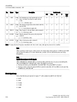
Note: "X" means that the DI signal is not effective for this control mode, although the value can be modified.
Note
When working in the torque control mode, the torque setpoint equals to 0 if CWE and CCWE
are at the same status. For more information, please refer to section Direction and stop
(Page 263).
Note
Invalid circumstances for DI signals
When SINAMICS V-ASSISTANT is communicating with the drive or you are operating the
drive on SINAMICS V-ASSISTANT, some DI signals are invalid:
•
During referencing via SINAMICS V-ASSISTANT, DI signal SREF is invalid.
•
During a trial run test, DI signal SON is invalid; meanwhile, DI7 and DI8 are occupied by
SINAMICS V-ASSISTANT.
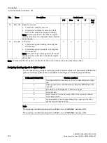
Direct signal map
Force the following six signals to logical "1" with parameter p29300 (P_DI_Mat):
●
SON
●
CWL
●
CCWL
●
TLIM1
●
SPD1


