


Parameters
10.2 Parameter list
SINAMICS V90, SIMOTICS S-1FL6
Operating Instructions, 04/2019, A5E36037884-007
377
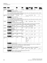
Par. No.
Name
Unit
Data type
Note: The value of -200 indicates that there is no measuring signal.
•
r0037[0]: Maximum value of the inverter temperatures (r0037[5...10]).
•
r0037[1]: Maximum value of the depletion layer temperatures (r0037[13...18]).
•
r0037[2]: Maximum value of the rectifier temperatures (r0037[11...12]).
The maximum value is the temperature of the hottest inverter, depletion layer, or rectifier.
r0079[
0...1
]
Torque setpoint total
Nm
Float
Description: Displays and connector output for the torque setpoint at the output of the speed controller (before
clock cycle interpolation).
Index:
•
[0]: Unsmoothed
•
[1]: Smoothed
r0296
DC link voltage undervoltage threshold
V
U16
Description: Threshold to detect a DC link undervoltage.
If the DC link voltage falls below this threshold, the drive unit is tripped due to a DC link undervoltage condi-
tion.
Note: The value depends on the device type and the selected device rated voltage.
r0297
DC link voltage overvoltage threshold
V
U16
Description: If the DC link voltage exceeds the threshold specified here, the drive unit is tripped due to DC link
overvoltage.
Dependency: Refer to F30002.
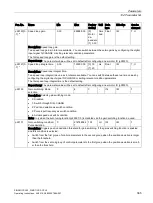
r0311
Rated motor speed
rpm
Float
Description: Displays the rated motor speed (rating plate).
r0333
Rated motor torque
Nm
Float
Description: Displays the rated motor torque.
IEC drive: unit Nm
NEMA drive: unit lbf ft
r0482[0...2
]
Encoder actual position value Gn_XIST1
-
U32
Description: Displays the encoder actual position value Gn_XIST1.
Index:
•
[0]: Encoder 1
•
[1]: Encoder 2
•
[2]: Reserved
Note:
•
In this value, the measuring gear is only taken into account when the position tracking is activated.
•
The update time for the position control (EPOS) corresponds to the position controller clock cycle.
•
The update time in isochronous operation corresponds to the bus cycle time.
•
The update time in isochronous operation and with position control (EPOS) corresponds to the position
controller clock cycle.
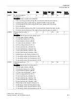
•
The update time in non-isochronous operation or without position control (EPOS) comprises the following:
–
Update time = 4 * least common multiple (LCM) of all current controller clock cycles in the drive group
( drives). The minimum update time is 1 ms.
–
Example 1: infeed, servo
Update time = 4 * LCM(250
μs, 125 μs) = 4 * 250 μs = 1 ms
–
Example 2: infeed, servo, vector
Update time = 4 * LCM(250 μs, 125 μs, 500 μs) = 4 * 500 μs = 2 ms


