Control functions
7.8 Communicating with the PLC
SINAMICS V90, SIMOTICS S-1FL6
272
Operating Instructions, 04/2019, A5E36037884-007
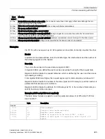
Description
Comment
⑤
Set the monitor time for Modbus by parameter
p29019.
Sets the monitoring time to monitor the process data received
via the RS485 interface. If no process data is received within
this time, then F1910 is output.
The default vaule of p29019 is 0. If p29019 = 0, monitoring is
deactivated.
⑥
Set control mode for the drive by p29003.
⑦
Save the parameters and restart the drive.
⑧
Configure the PLC parameters.
Note:
Keep the PLC baud rate the same as the drive setting.
Set even parity check for the PLC.
⑨
Set a way for PLC sending message to slaves.
Note:
For broadcast mode, you need to set the slave address to 0
on the PLC side.
For unicast mode, you need to set the desired target slave
address on the PLC side. For example, if you want to send
the message to slave 1, you need to set the slave address to
1 on the PLC side.
⑩
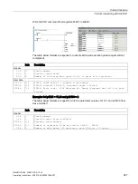
Write the control word via PLC.
Note:
Bit 10 of the register 40100 must be set to 1 to allow the PLC
to control the drive.
You need to trigger a rise edge for OFF1 to enable SON sta-
tus for the motor, and OFF2 and OFF3 must be set to 1. The
step must be executed when you enable SON for the first
time.
⑪
Write the setpoint and read the status word via PLC.
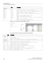
Example 1
This example shows the operating procedures when we use the setpoint and control word
from Modbus (p29008 = 1) as the Modbus control source in S control mode.
1.
Set RS485 bus address for the drive.
•
p29004 = 1
2.
Select the Modbus protocol by p29007.
•
p29007 = 2
3.
Select Modbus control source by p29008.
•
p29008 = 1
4.
Set the transmission baud rate by p29009.
•
p29009 = 8 (38400 baud)
5.
Set the drive work mode to S control mode.
6.
Save the parameters and restart the drive.

