Control functions
7.6 Speed control (S)
SINAMICS V90, SIMOTICS S-1FL6
258
Operating Instructions, 04/2019, A5E36037884-007
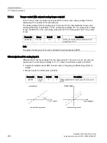
7.6.1.2
Speed control with fixed speed setpoint
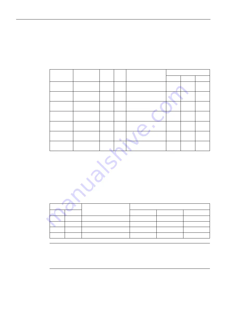
Parameter settings
In the S mode, when at least one of the three digital input signals SPD1, SPD2 and SPD3 is
at high level, one of the following parameter values is used as speed setpoint.
Parameter
Range
Default Unit
Description
Digital input
SPD3 SPD2 SPD1
p1001
-210000 to
210000
0
rpm Fixed speed setpoint 1
0
0
1
p1002
-210000 to
210000
0
rpm Fixed speed setpoint 2
0
1
0
p1003
-210000 to
210000
0
rpm Fixed speed setpoint 3
0
1
1
p1004
-210000 to
210000
0
rpm Fixed speed setpoint 4
1
0
0
p1005
-210000 to
210000
0
rpm Fixed speed setpoint 5
1
0
1
p1006
-210000 to
210000
0
rpm Fixed speed setpoint 6
1
1
0
p1007
-210000 to
210000
0
rpm Fixed speed setpoint 7
1
1
1
7.6.2
Direction and stop
Two digital input signals are used to control motor direction and run/stop.
●
CWE: clockwise enable
●
CCWE: counter-clockwise enable
The following table shows you in details:
Signal
Fixed torque setpoint
Analog torque setpoint
CCWE
CWE
+ polarity
- polarity
0 V
0
0
0
0
0
0
0
1
CW
CW
CCW
0
1
0
CCW
CCW
CW
0
1
1
0
0
0
0
Note
In S mode or T mode, when the servo motor is ready to run, signal CWE or CCWE is a must
to start running the motor.
For more information about signals CWE and CCWE, refer to "DIs (Page 123)".


